
Shimge Pump Industry Group Co., Ltd.,
Price Negotiable
Shipping Notes: Please contact us for more details.
Sample Policy: We offer samples, with sample costs, shipping and taxes paid by the buyer
Product Information
Related Products from this Supplier
View All
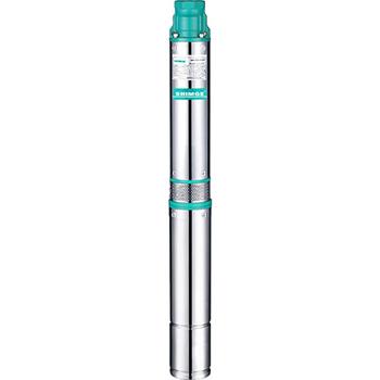
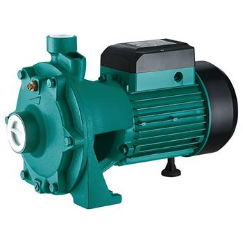
Description
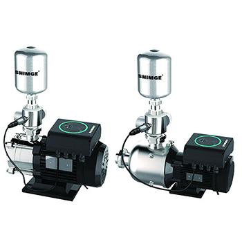
BW(J)E and BL(T)E series fully integrated intelligent variable frequency pump is a new generation of pressurized water supply equipment newly developed by us which highly integrates variable frequency controller, water pump and pressure tank; with handsome appearance, the pump has reached the international advanced level; provided with artificial intelligence, it can adjust automatically to meet the user’s requirement for constant pressure and variable frequency water supply, so as to keep constant the pressure of water supply network and maintain the whole system at the optimal energy-efficient state.
Send Inquiry Application FieldsDomestic water supply: Roof pressurization for high-rise building, apartment, and villa, etc.Public places: School, restaurant, station, hospital, and gymnasium, etc.Commercial buildings: Hotel, office building, and department store, etc.Irrigation: Farm, orchard, and park, etc.Industry: Manufacturing, food industry, industrial water supply and other places requiring constant pressure water supply.Operating Conditions Operating voltage AC220V±10%, 50HZ, with interphase unbalance less than 2%.Ambient temperature -5°C ~ 40°C;The altitude at the installation site is no more than 1000m; Ambient humidity 10-90%RH (non-condensing); There is no medium with explosive risk in the ambient air, and there is no gas or conducting dust which is enough to corrode metal and damage insulation in ambient media. The product is designed to operate in the environment with the pollution class II.Model Definition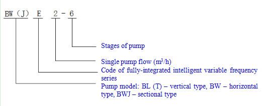 FunctionsWhen water is used, the system is kept at constant pressure by variable control; when water is not used, the system pressure is automatically maintained with the pump shut down.The operating pressure fluctuation range of variable frequency pump is no more than 0.01MPa.The pump shuts down if it idles without water. The pump has the function of detecting such faults as disconnection, overcurrent, overload, and earthing. Characteristics Frequency converter: With the protection class of IP65, it’s safe and reliable. High integration: Water pump and frequency converter are integrated with small volume, easy to install and space saving. Full-automatic control: The pump can automatically adjust its operating state according to the user’s pipe network pressure to reach the optimal operating state and make the system more energy-saving. When no water is used, it automatically maintains the pressure and goes to sleep, with obvious energy-saving effect. When the pump breaks down, it automatically performs real-time tracking, judgment and handling.Convenient and simple operation: Man-machine interaction can be realized directly through buttons and display at the frequency converter, and the user can make pressure-related settings according to the actual operating conditions, and obtain relevant information; in case of any abnormality, the user can obtain information about the abnormality. Constant-power operation: When the controller reaches the limit power, it adjusts according to actual operating conditions; with water supply for the user guaranteed wherever possible, the output power is unchanged to realize protection of the motor. Action specification
 The automatic identification module senses the system pressure through pressure sensor, compares it with the set pressure, and outputs continuous analog signal to the frequency converter, and then the variable frequency controller changes the operating frequency of motor according to the change of analog signal so as to reach the requirement for constant water supply. When the user’s water consumption is large, the pump automatically increases the rotating speed and power to meet the requirement for constant water supply. When no water is used, the pump automatically sleeps after the system reaches the set pressure, and only when the water pressure drops to 80% because the user uses a small amount of water or the pipeline leaks, the variable frequency controller sends signal to order the motor to operate to compensate the pressure to the set pressure, so as to realize energy saving to the greatest extent.
Equipment Type Spectrum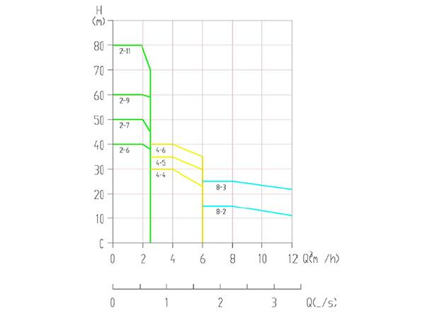 Performance Parameters No. Model Input voltage Constant pressure Setting range kg/cm² Constant pressure set at delivery (rated pressure) kg/cm2 Inlet diameter Outlet diameter Single pump power kW Max. lift (zero flow) m Rated flow m3/h Volume of pressure tank L A03 BW(J)E2-6 1ΦAC220V 0.5-4 4 G1 G1 0.75 56 2 3 A05 BW(J)E4-4 1ΦAC220V 0.5-3 3 G1 G1 0.75 38 4 3 A06 BWJE4-5 1ΦAC220V 0.5-3.5 3.5 G1 G1 1.1 47 4 3 A07 BWJE4-6 1ΦAC220V 0.5-5 3 G1 G1 1.1 57 4 3 A08 BWE8-2 1ΦAC220V 0.5-1.5 2 G2 G2 0.75 22 8 5 A09 BWE8-3 1ΦAC220V 0.5-2 2 G2 G2 1.1 32 8 5 A12 BWJE8-2 1ΦAC220V 0.5-1.5 1.5 G1 G1 0.75 22 8 5 A13 BWJE8-3 1ΦAC220V 0.5-2 2 G1 G1 1.1 32 8 5 B03 BL(T)E2-6 1ΦAC220V 0.5-4 4 G1 G1 0.75 58 2 3 B04 BL(T)E2-7 1ΦAC220V 0.5-5 5 G1 G1 0.75 68 2 3 B05 BL(T)E2-9 1ΦAC220V 0.5-6 6 G1 G1 1.1 87 2 5 B06 BL(T)E2-11 1ΦAC220V 0.5-8 8 G1 G1 1.1 106 2 5 B09 BL(T)E4-4 1ΦAC220V 0.5-3 3.5 G1 G1 1.1 50 4 3 B09 BL(T)E4-5 1ΦAC220V 0.5-3.5 3.5 G1 G1 1.1 50 4 3 B10 BL(T)E4-6 1ΦAC220V 0.5-4 4 G1 G1 1.1 58 4 3 B14 BL(T)E8-2 1ΦAC220V 0.5-1.5 1.5 DN40 DN40 0.75 22 8 5 B15 BL(T)E8-3 1ΦAC220V 0.5-2 2 DN40 DN40 1.1 32 8 5 Overall Dimensions of Variable Frequency Pump
 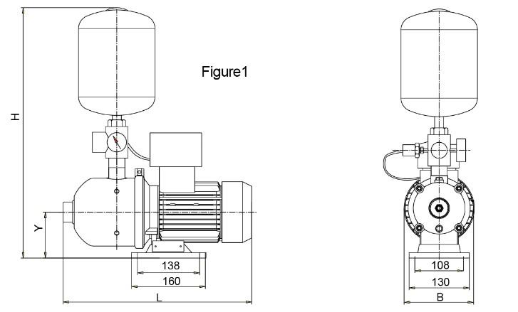 No. Model L L1 B H H1 Schematic diagram A03 BW(J)E2-6 402(445) 165(151) 220 630 140 1 A05 BW(J)E4-4 419(445) 168(151) 220 630 140 1 A06 BWJE4-5 472 178 220 630 140 1 A07 BWJE4-6 499 232 220 630 140 1 A08 BWE8-2 539 272 227 680 148 1 A09 BWE8-3 539 272 227 680 148 1 A12 BWJE8-2 376 111 227 680 148 1 A13 BWJE8-3 406 141 227 680 148 1
 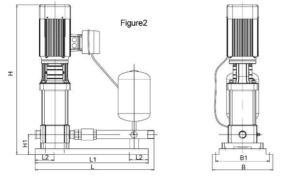 No. Model L L1 L2 B B1 H1 H1 Schematic diagram B03 BL(T)E2-6 610 550 100 320 280 80 587 2 B04 BL(T)E2-7 610 550 100 320 280 80 605 2 B05 BL(T)E2-9 610 550 100 320 280 80 641 2 B06 BL(T)E2-11 610 550 100 320 280 80 644 2 B08 BL(T)E4-4 610 550 100 320 280 80 587 2 B09 BL(T)E4-5 610 550 100 320 280 80 587 2 B10 BL(T)E4-6 610 550 100 320 280 80 641 2
  No. Model L L1 L2 B B1 H1 H Schematic diagram B14 BL(T)E8-2 750 700 100 360 320 120 652 3 B15 BL(T)E8-3 750 700 100 360 320 120 652 3 Appendix I: Installation Method
Schematic installation diagram
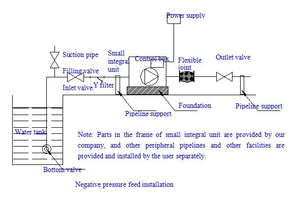
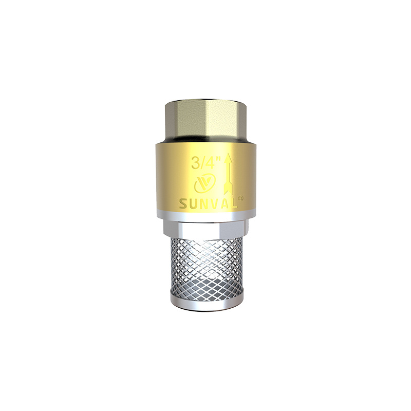
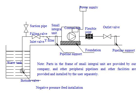 Precautions for Installation The pump should be installed in an indoor place free from water drop, metal dust, oily dust, corrosive or inflammable gas or liquid, and disturb of electromagnetic signals. When it’s installed outdoors, it should be provided with sheltering device.The ground for installation of variable frequency pump must be firm without sinking or cracking.At the installation of equipment, inlet positive pressure installation should be adopted, avoiding negative pressure suction installation wherever possible. If negative pressure installation must be adopted, please select a bottom valve with good quality, and carry out periodical maintenance. The inlet pipe and outlet pipe of variable frequency pump must be larger than the pipe diameter of the pump in diameter. Please note whether the power supply provided meets the requirement for incoming power supply of variable frequency pump.At installation, the user should provide inlet and outlet valves for variable frequency pump, and flexible joints for connection, which facilitate maintenance and prevent noise from transmitting through pipeline.When inlet positive pressure installation is adopted, please open the vent valve of pump to exhaust air before use, and close it until water comes out. When inlet negative pressure installation is adopted, please fill the suction pipe with water (a filling valve needs to be installed at suction pipe) before use, and start the pump after the pump cavity is filled with water. Appendix II: Selection Guide
Method of Calculating the Maximum Water Consumption No. Name of water supply fittings Rated flow (L/s) Equivalent Nominal diameter of connecting pipe (mm) Min. operating pressure (MPa) 1 Sink, mop basin, and bathroom sink Single-valve tap Single-valve tap Mixing tap 0.15~0.20 0.30~0.40 0.15~0.20(0.14) 0.75~1.00 1.5~2.00 0.75~1.00(0.70) 15 20 15 0. 050 2 Lavatory Single-valve tap Mixing tap 0.15 0.15 (0.10) 0.75 0.75(0.50) 15 15 0. 050 3 Hand basinInductive tap Mixing tap 0.10 0.15(0.10) 0.50 0.75(0.5) 15 15 0. 050 4 Bathtub Single-valve tap Mixing tap (with shower converter) 0.20 0.24(0.20) 1.00 1.2(1.0) 15 15 0. 050 0. 050~0.0 70 5 Shower Mixing valve 0.15(0.10) 0.75(0.50) 15 0. 050~0.100 6 Closet pan Ball float valve of flush tank Time-lapse self-closing flushing valve 0.10 1.20 0.50 6.00 15 25 0.020 0.10~0.15 7 Urinal Manual or automatic self-closing flushing valve Inlet valve of automatic flush tank 0.10 0.10 0.50 0.50 15 15 0.0 50 0. 020 8 Perforated flushing pipe for urinal trough (per meter) 0.05 0.25 15~20 0. 015 9 Flushing tap of bidet 0.10(0.07) 0.50(0.35) 15 0.0 50 10 Hospital bedpan flusher 0.20 1.00 15 0. 050 11 Laboratory water tap (gooseneck) Single Double Triple 0.07 0.15 0.20 0.35 0.75 1.00 15 15 15 0. 020 0. 020 0. 020 12 Drinker nozzle 0.05 0.25 15 0.0 50 13 Sprinkler head 0.40 13 Sprinkler head 0.40 14 Indoor floor flushing tap 0.20 1.00 15 0. 050 15 Domestic washing machine tap 0.20 1.00 15 0.050 Notes
Numerical values in brackets in the table are used for calculating cold water or hot water separately when hot water is available;When a bathtub is attached with a shower, or a mixing tap has shower change-over switch, the rated flow and equivalent shall be calculated by water tap but not the shower. However, water pressure shall be calculated by the shower;The water pressure required for domestic gas water heater shall be determined according to the product requirements and the operating pressure required for the most unfavorable distribution point of the hot water supply system; Automatic spray irrigation for greenbelt shall be designed according to product requirements;When special requirements are set for the rated flow and minimum operating pressure of water supply fittings of sanitary ware, the value shall be determined according to product requirements. (How to determine the equivalent when product requirements are set)Calculation of maximum water consumption
L = number of single-valve tap * rated flow + mixing tap * rated flow + ······ + number of domestic washing machines * rated flowThe unit of calculated L is (L/S), and it should be multiplied by 3.6 when the unit is converted to T/H. (See Table 1 for rated flow)Calculation of minimum pressure
The minimum pressure shall be calculated from the water suction level of water pump plus the minimum necessary pressure of the highest sanitary ware used.
Minimum service pressure of water supply equipment (Mpa) ≈1/100*(hg+hf)+pe
Ha: Actual lift from water suction level to the highest sanitary ware (m)
Hf: Head loss of pipelines and bends (m), which may take 6m-10m.
Pe: Minimum necessary pressure of the highest sanitary ware (see Table 1)
Example: A small hotel, which has four over-ground floors with the height of about 12m (from the water suction level), has 12 rooms in the hotel, and each room is equipped with one closet pan, one hand basin (mixing tap), and one shower (mixing tap); in addition, the hotel has one water tap for washing machine, four indoor floor flushing taps, and four drinker taps. Please calculate the flow and lift of water supply equipment to be used.
Solution: Calculation of maximum water consumption:
Maximum water consumption: 3.6 {12 (1*0.1+1*0.15+1*0.24) + 1*0.2 + 4*0.2 + 4*0.05} = 6.084 T/H
Minimum pressure:
Minimum pressure ≈1/100* (12+10)+0.07=0.29 Mpa
Ha: The actual lift from water suction level to the highest sanitary ware is 12m.
Hf: Head loss of pipelines and bends take 10m.
Pe: The minimum operating pressure of shower is 0.7 bar.
Note: 1bar≈1kg/cm2=0.1Mpa, 1Mpa is approximately equal to the pump lift of 100m.
When selecting equipment, the total flow of selected equipment is the maximum water consumption, and the lift is no less than the calculated minimum pressure; please refer to the equipment type spectrum.
Packaging & Logistics
RTS
Payment details are for reference only. Please contact supplier for exact terms.
Company Introduction
Shimge Pump Industry Group Co., Ltd., established in 1984 in Daxi Town, Wenling City of Zhejiang Province, the center of Chinese water pump industry, is a listed joint-stock company specialized in the production and operation of pumps and control equipment. In the past three decades, it has been focusing on the technical research, production and marketing of pump products and control equipment, and has been devoted itself to providing the best pumps and water treatment system solutions for the world. Currently, the company has five business divisions (including submersible pump, surface pump, well pump, canned motor pump and stainless steel pump), six production bases and ten holding subsidiaries. On December 31, 2010, SHIMGE landed on the A-share market, and was successfully listed on Shenzhen Stock Exchange (stock code: 002532).
Since its establishment, the company has always actively promoted comprehensive "lean" quality and environment management, and has currently passed ISO9001, ISO14001 and OHSAS18001 certification, introduced excellent performance management in line with GB/T 19580 and established a sound quality assurance system. SHIMGE is equipped with an industry-leading physicochemical testing center, and its delivery performance inspection platform has reached a precision of grade B (grade 1) in the evaluation conducted by an authoritative agency. In addition, its products have passed GS, CE and UL certification, and met the specifications of the RoHS Directive.
As a "hi-tech enterprise", the company has gathered many talents in the industry in the fields of technical innovation and product R&D, and has established technical cooperation with many scientific research institutions and colleges and universities with outstanding achievements in the water conservancy, such as Jiangsu University, China Agricultural University, Wuhan University, Zhejiang University, etc. In 2010, the company was elected as one of the first batch of pilot units as "Post-doctoral Scientific Research Stations" in Zhejiang Province; in 2013, it established the technical R&D-oriented SHIMGE Pump (Hangzhou) Co., Ltd., which was intended to focus on the R&D of automated and intelligent products and awarded the title of "Most Innovative Enterprise in China" in the same year. In 2014, the experiment center of the company passed CNAS laboratory certification at the first try, and became a national level laboratory. So far, the company has directed or participated in the revision of more than 50 national and industrial standards, and obtained a total of 125 authorized patents.
In terms of channel building and after-sales services, relying on its strength and public reputation as a leading brand in the industry as well as its excellent product quality, the company has developed a global business network, established 15 regional distribution centers in all major provinces and cities in China, and built cooperative relations with more than 1,100 wholesalers and 4,000 distributors to provide better services to its clients. Since 2006, SHIMGE has occupied the first place nationwide in terms of the production and sales of agricultural pumps for nine consecutive years (according to the authoritative data statistics of China Association of Agricultural Machinery Manufacturers (CAAMM)), and, in the international pump market, SHIMGE products have been sold to more than 100 countries and regions all over the world and enjoy high reputation.
Mission
The mission of the company is to provide the best pumps and water treatment system solutions for the world and create high-quality life for the mankind.
Contact Information
Shimge Pump Industry Group Co., Ltd.,contact_person
shimge
Address
Dayangcheng Industrial Zone, Daxi Town, Wenling City, Zhejiang Province, China
send_inquiry
send_inquiry_description