This is the internet's most comprehensive description of roll forming.
You'll discover:
- The fundamentals of roll forming
- Roll forming techniques
- Recent technological advancements
- Key benefits and advantages
- Suitable metals for roll forming
- And additional valuable information
Chapter One – Understanding Roll Forming
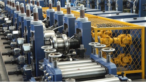
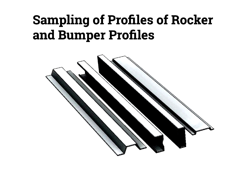
Roll forming is a precision metalworking process that uses sequentially arranged rollers to gradually shape a continuous metal strip. These rollers, organized in multiple stands, each perform specific bending operations to achieve the final form.
The rollers are carefully engineered using a flower pattern that maps the metal strip's progressive transformations. Each roller's unique shape corresponds to specific segments within this pattern.
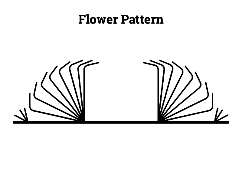
The flower pattern's colors represent individual bending stages required to create the final product. Engineers use CAD/CAM simulations to model the process before production, allowing them to select optimal calibrations and profiles for various bending angles. This digital approach enables rapid design of new shapes with simple software commands.
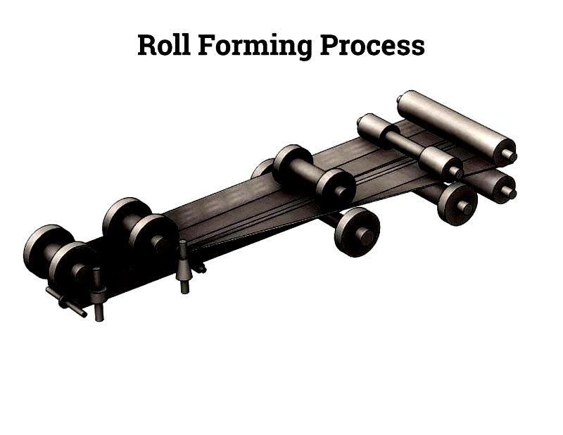
Chapter Two – The Roll Forming Process
While manufacturers may implement unique operational sequences, all roll forming processes share fundamental steps that define this metal fabrication method. Understanding this standardized workflow facilitates better comparison between manufacturers and helps assess production capabilities, precision, and customization options.
The process begins with large metal coils, typically 1-30 inches wide and 0.012-0.2 inches thick. Materials range from cold-rolled steel to aluminum, selected based on application requirements. Proper coil preparation ensures accurate results and high-quality finished profiles.
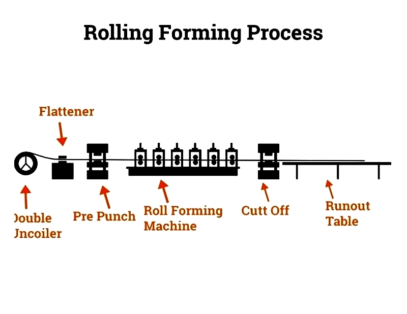
The diagram above shows the complete roll forming sequence, from automated coil feeding to final cutoff and discharge. Below we detail each critical phase of the manufacturing process.
Roll Forming Process Steps
Uncoiling
Extended storage can cause metal coils to retain their wound shape, potentially leading to feeding issues. The coil is mounted on an industrial uncoiler and passed through a straightener to ensure flatness. The leading edge is precisely trimmed for smooth feeding into pre-press equipment. Proper uncoiling prevents jams and dimensional inconsistencies.
Pre-press operations may include tapering the coil's leading edge to facilitate roller entry and reduce startup scrap, particularly important for high-volume production.

Pre-press Treatment
Before forming, automated pre-press operations may include punching, stamping, or adding features like slots or holes. These integrated processes reduce secondary machining needs and ensure precise feature placement. The image below shows a pre-punching system commonly used in custom roll forming for construction and automotive applications.

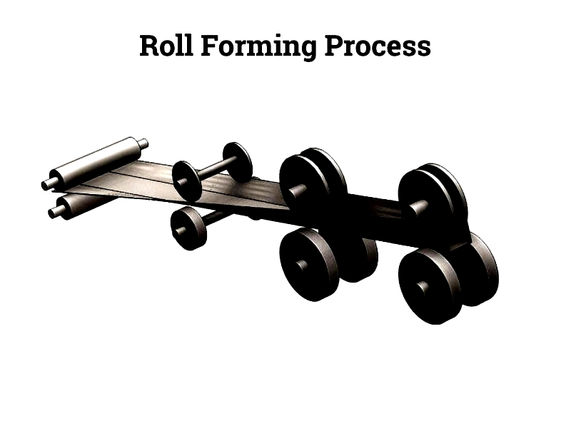
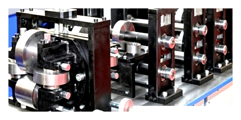
Roll Forming
In this critical stage, 10-24 paired roller dies gradually shape the metal strip into the desired profile. Advanced CNC-controlled machines ensure consistent tolerances for complex shapes used in roofing, automotive, and building components. This method excels at producing long, uniform sections with minimal waste compared to alternative forming techniques.
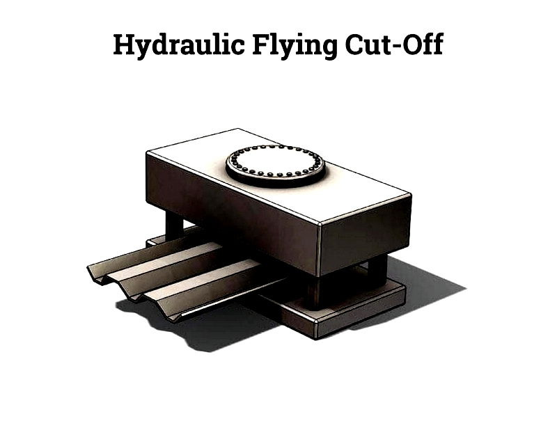
Cutoff and Discharge
A flying cutoff die trims the continuous profile to precise lengths during movement, maintaining dimensional accuracy. Cut parts are automatically transferred for collection, inspection, or further processing, supporting efficient production workflows.
Secondary Processes
Additional finishing steps may include punching, welding, or assembly, performed either in-line or at separate workstations. These processes expand roll forming's versatility for demanding applications in construction, automotive, and industrial sectors.
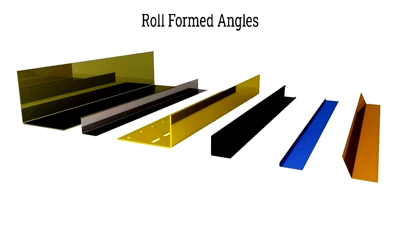
Examples include complex automotive profiles and custom building components, as shown below.
- Precision punching
- Notching operations
- High-tolerance forming
- Profile straightening
- Component integration
- Assembly processes
Lubrication
Proper friction management is essential for tool life, surface quality, and dimensional accuracy. Friction between rollers and metal generates heat that can accelerate tool wear if uncontrolled. Line speed and material type influence friction levels.
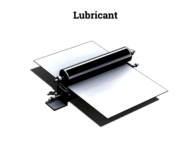
Appropriate lubricants reduce friction while maintaining optimal material flow. Selection depends on material, profile complexity, speed, and finishing requirements. Modern operations favor eco-friendly, low-viscosity lubricants that improve efficiency while meeting environmental standards.
Advanced lubrication systems ensure consistent coverage while minimizing residue. The example below shows chlorine-free lubricants meeting sustainability requirements.
 This Rolling Forming Machine Uses a Chlorine Free Lubricant
(from etna.com)
Process Advantages
Roll forming excels at mass-producing long, precise metal profiles with complex cross-sections. Its automated nature reduces labor costs while improving consistency and material efficiency. The process adapts to diverse materials and applications across multiple industries.
When selecting a supplier, consider production capacity, tooling expertise, quality systems, and secondary processing capabilities. Manufacturer experience with specific applications ensures optimal process design and product performance.