Introduction
This section describes the applications of 400 series stainless steel grades 410, 416, and 420, their manufacturing processes, and purchasing options.
You will learn about:
- The characteristics of 400 series stainless steel grades 410, 416, and 420
- Manufacturing methods for these stainless steel grades
- Common applications for grades 410, 416, and 420
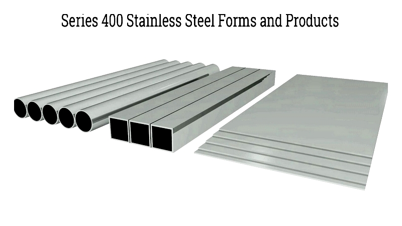
- Available forms of these stainless steel grades
- Additional relevant information
Chapter 1: Understanding 400 Series Stainless Steel
The 400 series stainless steels are characterized by their high carbon content, which provides excellent strength and wear resistance. While offering less corrosion resistance than austenitic stainless steels, this series can be hardened through heat treatment, making it suitable for demanding applications.
- Grade 410 is a versatile martensitic stainless steel that combines strength with moderate corrosion resistance.
- Grade 416, derived from 410, is the only free-machining stainless steel in this series, offering excellent machinability.
- Grade 420 provides superior hardness, making it ideal for applications requiring high durability and wear resistance.
Selection of 400 series stainless steels depends on specific requirements. These martensitic steels can be hardened through heat treatment, offering excellent hardness, strength, and wear resistance. Grade 410 serves as a general-purpose option, Grade 416 provides superior machinability, and Grade 420 delivers maximum hardness.
Grade 410 contains 11.5% chromium, providing moderate corrosion resistance that can be enhanced through polishing and heat treatment. This grade is commonly used for knife blades, scissors, culinary tools, and firearm components.
Grade 416 features improved machinability due to its sulfur and phosphorus content. With tensile strength ranging from 510 to 800 MPa and hardness between 230-320 HB, it offers a cost-effective solution for machining applications.
Grade 420 provides exceptional hardness and wear resistance, with hardness reaching 55+ HRC after heat treatment. While its corrosion resistance is moderate, polishing and tempering can improve performance. This grade is widely used for surgical instruments, cutting tools, and industrial blades.
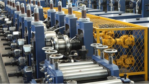
Chapter 2: Manufacturing Process for Series 400 Grades 410, 416, & 420
400 series stainless steels are engineered for specific industrial applications, featuring higher carbon content for enhanced strength and wear resistance. While less corrosion-resistant than 300 series austenitic grades, they excel in durability and machinability. The composition typically includes 11-27% chromium, up to 1% carbon, and about 2.5% nickel, with a primarily martensitic structure that varies in strength between grades.
The Manufacturing Process
Production of 400 series stainless steel involves multiple stages to ensure optimal performance:
-
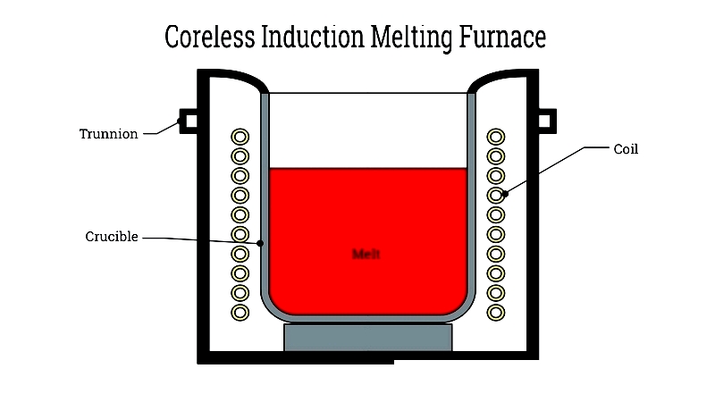
Melting: Raw materials are melted in electric arc or coreless induction furnaces at high temperatures for 8-12 hours to achieve homogeneous mixture.
-
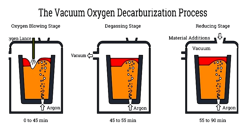
Carbon Removal: Vacuum oxygen decarburization (VOD) or argon oxygen decarburization (AOD) processes precisely control carbon content.
- Stirring: Ensures uniform distribution of alloying elements.
-
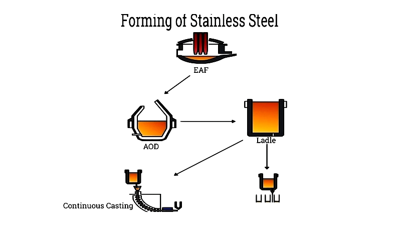
Forming: Molten steel is cast into billets, blooms, or slabs using continuous casting methods.
- Annealing: Heat treatment enhances grain structure and ductility.
-
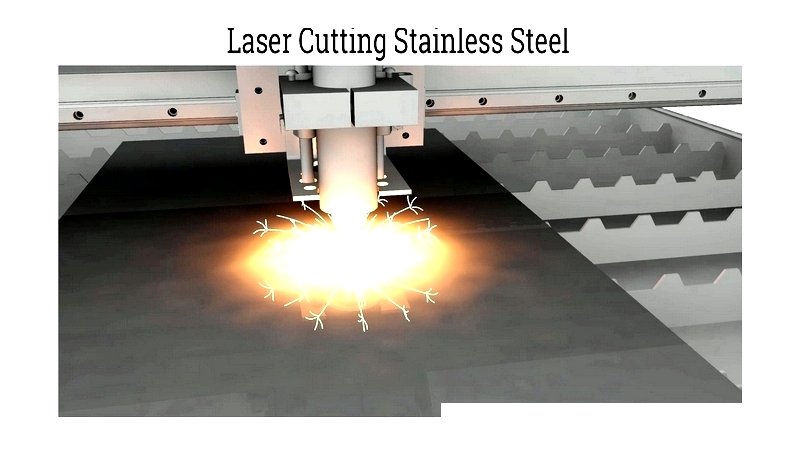
Cutting: CNC machining, laser cutting, and other methods create precise components.
- Finishing: Rolling, polishing, or abrasive blasting improves surface quality and corrosion resistance.
Chapter 3: Stainless Steel Grade 410
Grade 410 is a widely used martensitic stainless steel valued for its balanced properties. It offers good hardness, strength, and moderate corrosion resistance at a competitive cost. The manufacturing process includes melting, casting, hot working, and heat treatment to optimize performance.
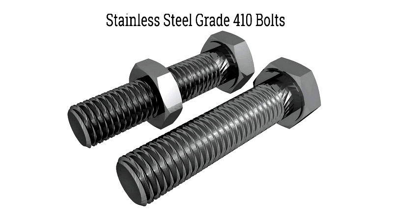
With 12% chromium content, Grade 410 provides oxidation resistance that can be enhanced through polishing and heat treatment. Its typical composition includes: