Introduction
This article provides an in-depth exploration of butt hinges.
It covers various aspects including:
- Principles of Butt Hinges
- Design Features and Manufacturing Process
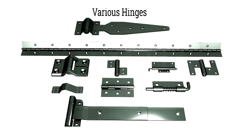
- Different Types of Butt Hinges
- Applications and Benefits
- Additional Relevant Information
Chapter 1: Fundamentals of Butt Hinges
This chapter examines the mechanics, functionality, and key factors for selecting appropriate butt hinges.
Defining Butt Hinges
As versatile connectors, hinges join two objects while permitting movement between them. Butt hinges feature rectangular plates attached to parallel surfaces, enabling a 180-degree swing range. Their main components include the knuckle, pin, and two leaves.
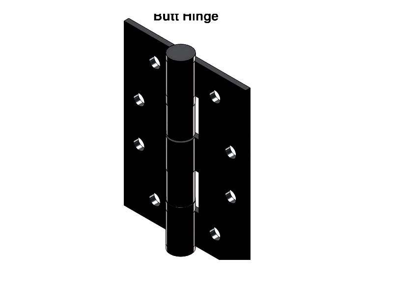
The leaves connect via a pin threaded through the knuckle. Typically mortised (requiring surface grooves), they're also called "mortise hinges." Comprising two equal-sized leaves with a prominent knuckle, these hinges allow flush closure when the leaves meet.
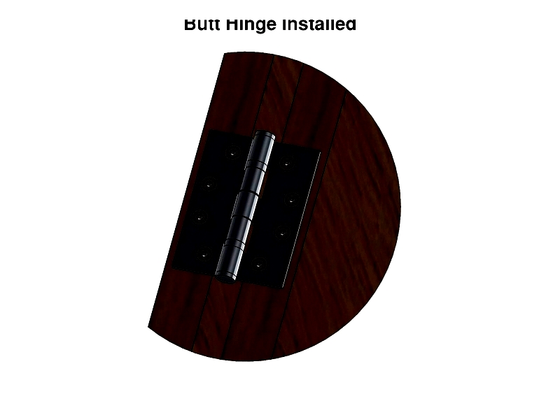
How Butt Hinges Work
Butt hinges facilitate smooth swinging motions for doors, gates, windows, and shelves. They support moving components while eliminating manual adjustments during operation. Typically, one leaf mounts on a fixed structure (door frame) and the other on a movable element (door). When closed, the leaves align flush with the knuckle forming a cylindrical barrel. Screws secure the leaves while a fixed or removable pin holds the knuckle.
Selection Criteria for Butt Hinges
When choosing butt hinges for various applications (cabinet doors, entry doors, exterior gates), consider these factors:
Load Capacity
Heavy doors/gates require durable materials like galvanized steel, stainless steel, die-cast zinc, or ABS.
Corrosion Resistance
For moist environments, opt for stainless steel, galvanized steel, aluminum, or nylon. Paint coatings enhance corrosion protection.
Heat Resistance
High-temperature settings demand heat-resistant materials like galvanized steel.
Impact Resistance
ABS materials withstand collision impacts effectively.
Durability
Material compatibility ensures longevity. Durable options include die-cast zinc, nylon, stainless steel, and galvanized steel.
Weight
Aluminum hinges suit lightweight components.
Maintenance
Stainless steel works well for frequently serviced hinges.
Aesthetics
Hinges should complement furniture/door designs visually.
Orientation
Choose left/right-handed versions based on door swing direction.
Chapter 2: Design and Manufacturing of Butt Hinges
This chapter explores design considerations and manufacturing techniques for butt hinges used in doors, cabinets, gates, and structural applications.
Design Characteristics
Key design elements include:
Leaf: Flat plates attached via screws/adhesives to surfaces.
Leaf Width: Determines load distribution and operation smoothness.
Leaf Length: Affects strength and weight capacity.
Leaf Thickness: Influences rigidity and warp resistance.
Knuckle/Barrel: Cylindrical joint housing the pin for rotation.
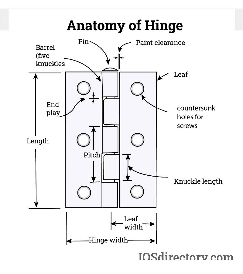
Pitch: Knuckle spacing affecting durability.
Paint Clearance: Prevents finish abrasion during movement.
Countersunk Holes: Enable flush screw mounting.
Pin: Central rod enabling rotation (fixed/removable).
End Play: Minimized axial movement reduces noise/wear.
Specialty features include ball bearings, security pins, corrosion-resistant coatings, and fire ratings.
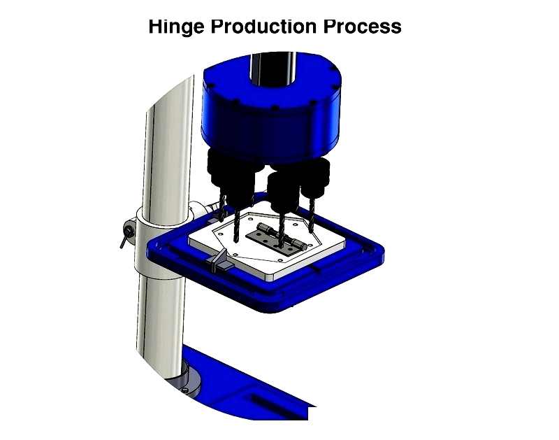
Manufacturing Processes
Production methods vary by material and application needs:
- Materials: Steel, stainless steel, brass, bronze, aluminum.
- Finishes: Polishing, plating, painting, powder-coating.
- Applications: Construction, furniture, marine, aerospace.
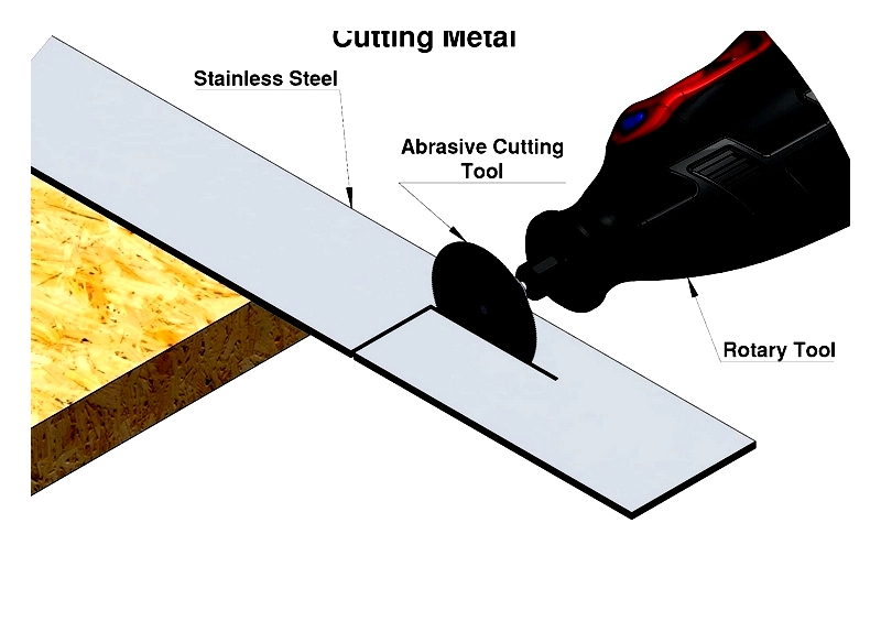
Manual Production
Custom hinges can be crafted by marking dimensions, cutting metal, filing edges, rolling knuckles, and drilling screw holes.
Heat Treatment/Cold Working
Heat treatment enhances durability; cold working improves tensile strength.
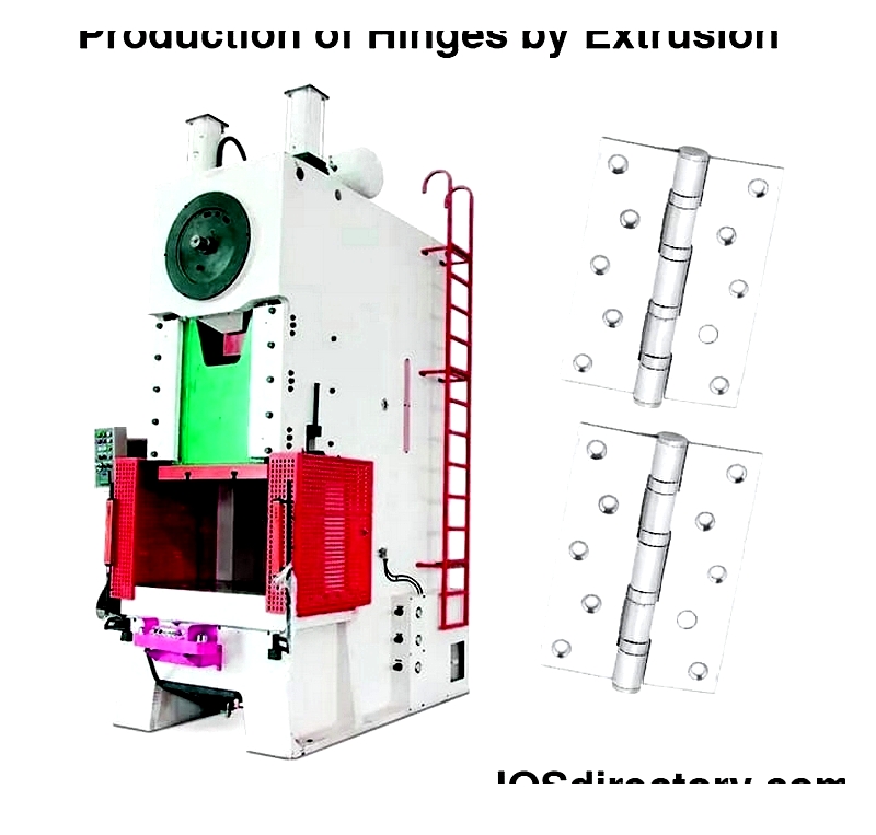
Extrusion
Creates strong, uniform profiles for demanding applications.
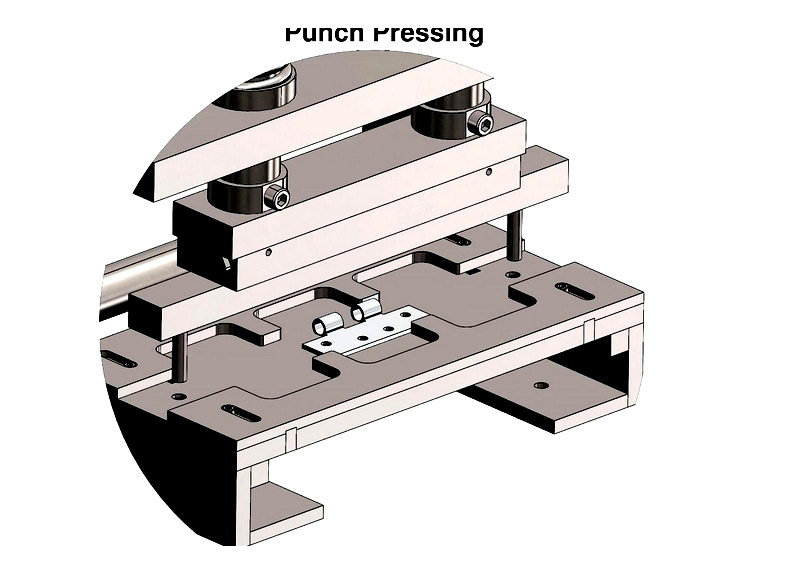
Stamping
Cost-effective mass production with precise dimensions.
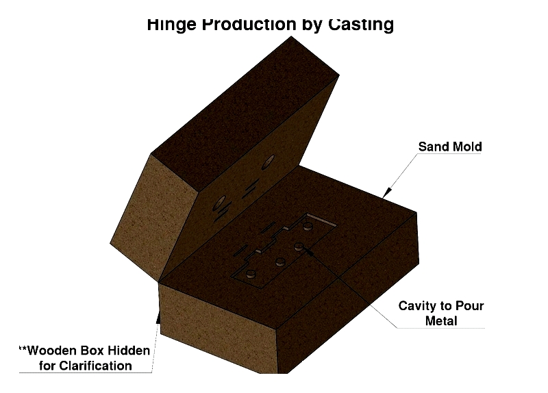
Casting
Ideal for complex/ornamental designs.
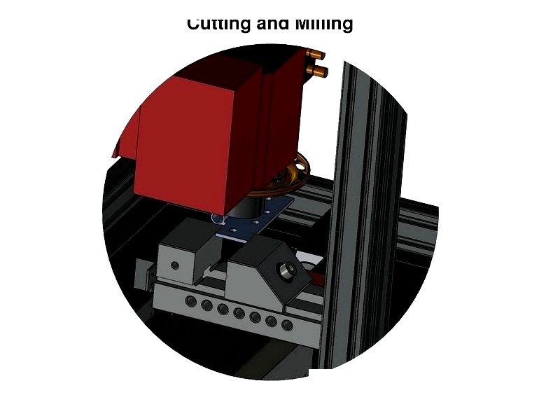
Cutting/Milling
Precision techniques for high-tolerance hinges.
Secondary Processing
Includes ball bearing installation and protective finishes for enhanced performance.
Understanding these manufacturing aspects helps in selecting appropriate butt hinges for specific projects.