Introduction
This article provides an in-depth exploration of radiant heaters.
Key topics covered include:
- Principles of Radiant Heaters
- Types of Radiant Heaters
- Applications and Benefits of Radiant Heaters
- And More...
Chapter 1: Understanding Radiant Heater Principles
This section examines the core principles behind radiant heaters, including their operation and unique design characteristics.
Definition of Radiant Heaters
Radiant heaters are devices that transfer warmth directly to objects and people, similar to sunlight. The warmth we feel from the sun comes from its infrared radiation.
Infrared heating uses electromagnetic waves to deliver energy directly to objects, bypassing the surrounding air. This method operates within the 0.7 to 6 micron (µ) range. By targeting specific wavelengths, infrared heating reduces energy waste and improves efficiency.
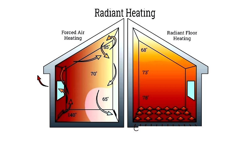
Unlike conventional heaters that warm the air, radiant heaters heat objects and people directly, avoiding the dry air associated with convection systems.
How Radiant Heaters Work
Radiant heaters produce heat internally and transmit it via electromagnetic waves, which convert to heat upon contact. These waves travel through air with minimal energy loss, warming surfaces like floors, walls, or people. Similar to how clothing absorbs sunlight, objects absorb radiant energy to provide warmth.
Radiant heaters can warm spaces without direct contact with the heat source, much like feeling the sun's warmth from a distance. This is especially useful in industrial settings where direct contact is impractical. Unlike conduction and convection, radiant heating relies on electromagnetic waves.
Radiant heaters transmit heat through electromagnetic waves without needing a transfer medium. Heat emission increases dramatically with temperature - doubling the temperature can produce up to 16 times more heat. Within the radiant field, warmth is felt directly from the source.
Even in cold air, absorbed radiant heat provides comfort. This principle is effectively used in products like tube space heaters. These decentralized systems convert energy to heat efficiently, unlike traditional central heating.
Key Components of Radiant Heaters
Main components include:
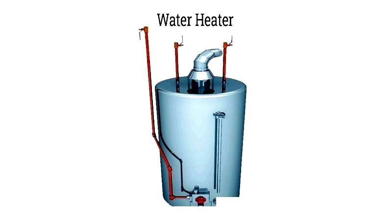
Water Heater
The system's core resembles a boiler. It heats water using gas or electric elements, then circulates it through pipes via a pump.
In-Floor Pipes
These pipes, typically PEX tubing, carry heated water through floors to provide warmth. They can be installed within, on, or below subfloors.
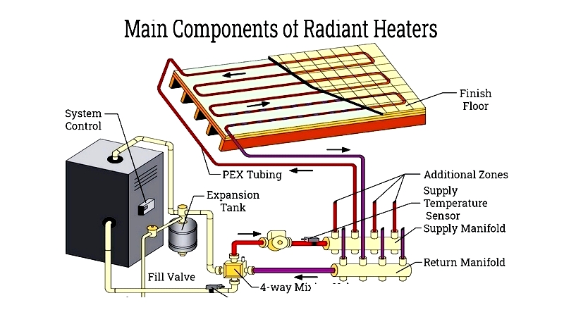
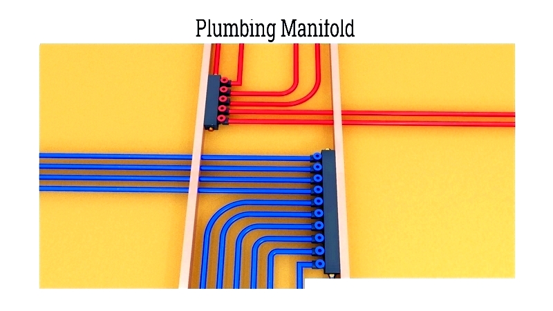
Plumbing Manifold
This component regulates water distribution between the tank and floor pipes. Its complexity depends on the number of zones requiring heating.
Designing a Radiant Heating System
Consider these factors when designing a system:
Calculate Heating Needs
Balance building heat loss with floor heat output. Determine required floor temperature by assessing heat loss, then select appropriate tube spacing and fluid temperature.
Calculate Heating Requirements Per Square Foot
Calculate heat loss per square foot based on temperature differences. For example, with 65°F indoors and -10°F outdoors, heat loss is 22.5 BTUs/hr per square foot.
Multiply Heat Loss by Temperature Difference
An 80°F floor can provide 27 BTUs/hr, sufficient for well-insulated spaces in cold conditions. Size heat sources by multiplying heat loss per square foot by total area.
Determine Heat Output
Estimate floor heat output. Outputs above 45 BTUs/hr may require floor temperatures exceeding 90°F. Consider supplemental heating if needed.
If radiant floors may be insufficient:
- Improve insulation to reduce heat loss
- Consider alternative radiant methods like slabs
- Add ceiling or wall heaters
- Use supplemental heat sources for extreme cold
Set Maximum Floor Temperatures
Keep functional maximum at 80°F, absolute maximum at 85°F.
Configure Tube Spacing
Space 1/2-inch tubes 8-12 inches apart for even heating.
Determine Tubing Length
Multiply floor area by spacing multiplier (e.g., 0.75 for 16-inch spacing).
Manage Circuit Length & Flow Rates
Avoid extremely short or long circuits. Ideal systems maintain 10-15°F temperature difference between inlet and outlet, with mild turbulence for effective transfer.
Chapter 2: Types of Radiant Heaters
Radiant heaters provide efficient warmth for residential, commercial, and industrial applications. They're chosen for consistent comfort, energy efficiency, and improved air quality compared to forced-air systems. Below we examine the main types, their installation, and ideal uses.
Electric Radiant Heating Systems
These systems use electric coils that generate heat when current flows through them. Insulated polymer sheets surround the coils. They can heat floors, walls, or ceilings depending on placement.
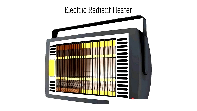
Common for floor heating, these systems require little maintenance and last long. They can be floor, wall, or ceiling mounted, making them versatile for various projects. However, operating costs can be high with rising electricity prices.
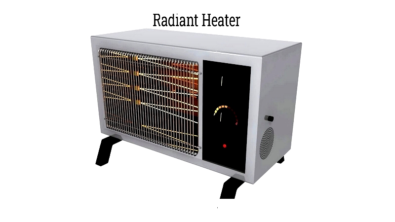
Best for small areas like bathrooms. Provide quick, targeted warmth ideal for spot heating or supplemental use.
Advantages: Quick installation, zoned control, better air quality, and compatibility with various flooring types.
Hydronic Radiant Heating Systems
These systems circulate heated water through pipes in floors, walls, or ceilings. They feature PEX tubing, thermostatic controls, and efficient pumps. While operating costs are lower than electric systems, leaks are possible.
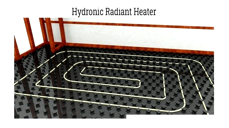
Most energy-efficient option for whole-house heating. Can use gas, propane, or solar-assisted heaters. Popular for green buildings and snow melting systems.
Common Uses: New construction, retrofits, large spaces, and driveway heating.
Air Radiant Heating Systems
These least efficient systems use heated air. Rarely used residentially, they may suit certain commercial or solar applications.
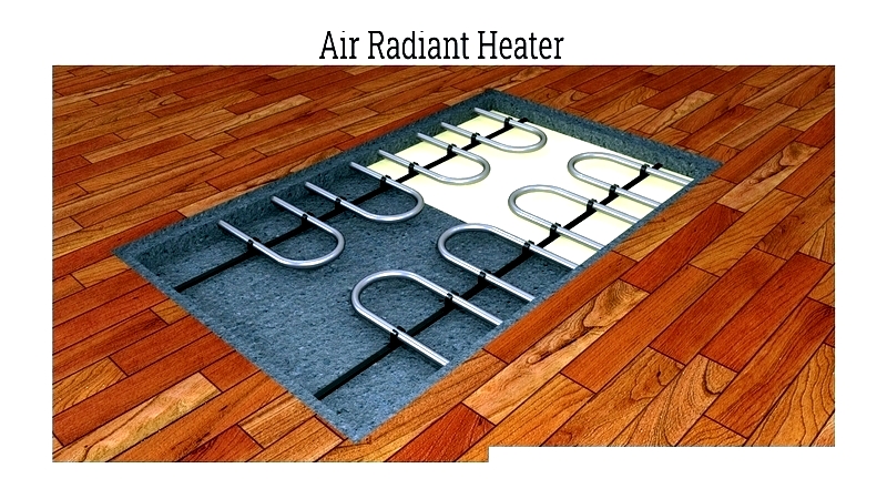
Potential uses include workshops or hybrid HVAC systems where air is readily available.
Examples of Radiant Heating Systems
Common examples include: