Introduction
This article provides an in-depth examination of different types of parts washers.
You will learn about various topics including:
- What is a Parts Washer?
- Basic Components of Parts Washers
- Applications of Parts Washers
- Types of Cleaners
- Types of Washing Processes
- Types of Parts Washers
- Parts Washer Accessories
Chapter 1: Understanding Parts Washers
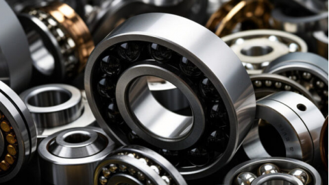
Parts washers are specialized industrial devices designed to clean various components by removing contaminants like grit, oil, grease, paint, and other residues. These machines accommodate parts of different sizes, from small millimeter-sized pieces to large, intricate instruments. They perform cleaning, degreasing, and drying operations to prepare parts for surface treatments, assembly, inspection, or shipping.
During manufacturing, components often accumulate unwanted substances such as oils, chemicals, burrs, and abrasive particles. Thorough cleaning is essential before coating or assembly to ensure contaminants don't interfere with surface treatments. Parts washers deliver exceptional surface purification, ensuring parts are free of impurities for smooth assembly and effective surface treatment application.
These washers use solvents, mechanical motion, and specialized chemicals to thoroughly clean surfaces, removing debris that could hinder further processing. This is particularly important in processes like electroplating, where clean, dry surfaces are crucial for optimal coating adhesion. Parts washers prevent potential issues, guaranteeing efficient and smooth coating application.
Chapter 2: Basic Components of a Parts Washer
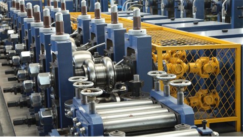
The core engineering of a parts washer focuses on effectively removing contaminants like oils, grease, metal chips, and debris from industrial and automotive components. The optimal design depends on factors such as part size, shape, and material composition. Parts can range from simple fasteners like nuts and bolts to complex components with varying weights, geometries, and hard-to-reach areas. More intricate parts often require automated equipment and advanced cleaning methods to meet cleanliness standards.
Leading parts washer manufacturers provide customized cleaning solutions for various applications, from light-duty tasks to large-scale industrial processes. Common industrial parts washer systems may include features like baskets, programmable CNC controls, automated loading, trays, conveyor belts, racking configurations, and rotary table mechanisms. The two main categories are aqueous (water-based) and solvent-based systems, differing primarily in their cleaning agents. Aqueous washers use water and detergents for eco-friendly cleaning, while solvent washers use organic solvents to dissolve contaminants.
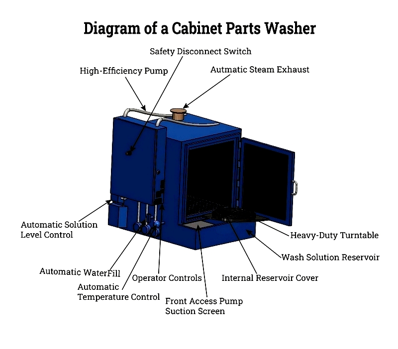
Despite design variations, most industrial parts washers share essential components for optimal operation and reliability. These include a high-efficiency water heater, multi-stage filtration system, industrial-grade pumps, mechanical or spray-action scrubbers and brushes, high-pressure nozzles, engineered tanks, and a durable enclosure for operator safety. Many modern units also feature automatic controls, programmable wash cycles, and smart sensor technology for energy efficiency and process optimization.
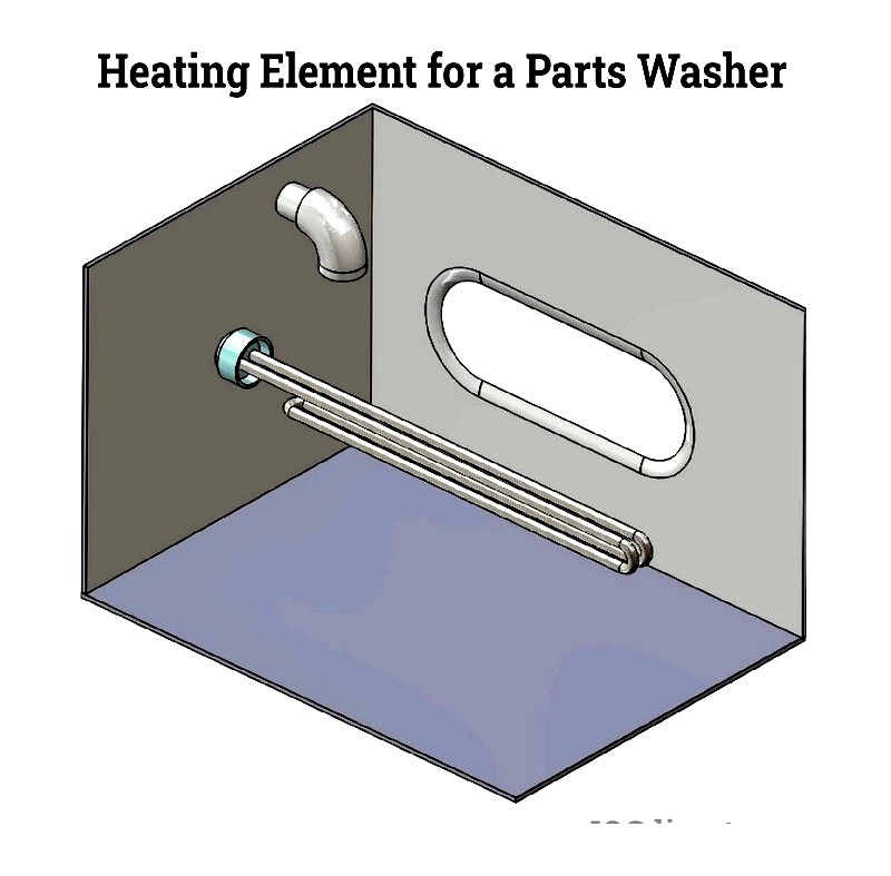
Water Heater
The water heater is crucial in both aqueous parts washers and heated solvent systems. Powered by gas, electricity, or steam, it raises the washing solution's temperature to enhance the chemical reaction between detergents and contaminants, ensuring effective cleaning. In high-throughput environments, efficient temperature control reduces cycle time while improving cleanliness. Advanced digital controls and thermostatic safety features are now standard, providing precise heat management and consistent results.
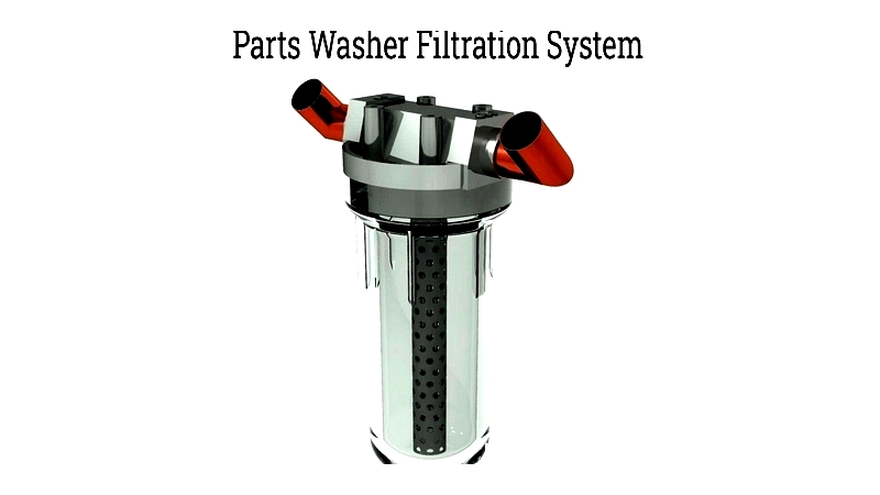
Filtration System
The filtration system continuously removes suspended solids like burrs, chips, and dirt from the cleaning solution. Positioned between the cleaning tank and solution reservoir, it extends the lifespan of detergents and washwater. Regular filtration ensures consistent cleaning performance and minimizes maintenance downtime. Options include single-pass cartridges, multi-stage filters, bag filters, magnetic traps, and oil skimmers. Automated monitoring alerts when filter media needs replacement, enhancing efficiency.
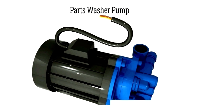
Pump
Industrial parts washer pumps recirculate cleaning solution through the system. Constructed from chemically resistant materials like stainless steel or polypropylene, they operate at high temperatures (up to 200°F/93°C) and elevated flow rates. Typical pumps move over 100 gallons per minute (GPM) at pressures exceeding 65 PSI. A robust pump maximizes cleaning coverage, whether powering spray nozzles, agitating bath-style washers, or rotary jets. Variable speed controls adjust flow for different parts and contamination levels.
Scrubbers
Scrubbers mechanically remove tough dirt, baked-on oils, and residues from parts. They may use rotating brushes, oscillating trays, or high-powered spray nozzles. The choice depends on part size, geometry, and sensitivity—delicate electronics require soft brushes, while robust castings withstand aggressive agitation. In automated systems, scrubber position and action are coordinated with tank design and solution flow to ensure uniform cleaning.
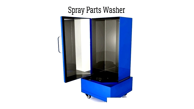
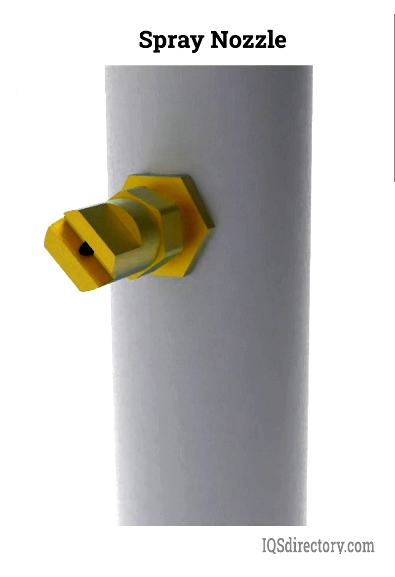
Nozzles
Nozzles are essential in spray-wash systems, available in designs like fan jets, full-cone, and multi-orifice tips. Proper configuration ensures uniform solution impingement for removing oils, grease, and contaminants. Advanced nozzles deliver variable patterns and pressures for different soil loads and part configurations. In cabinet parts washers, spray arms with precision nozzles provide thorough coverage for dense batches or complex assemblies. Nozzles in heated aqueous washers typically operate at 130°F to 200°F (54°C to 93°C) for optimal cleaning.
Tanks
Parts washer tanks are engineered to hold cleaning fluid and accommodate parts. Constructed from stainless steel or coated steel, they may feature compartments for sequential washing, rinsing, and drying to prevent cross-contamination. Industrial models often include sealed, insulated tanks for temperature uniformity and energy efficiency. Ultrasonic washers use tanks designed to transmit ultrasonic waves for microscopic contaminant removal.
Tank capacity and access design vary based on whether the washer is manual, automated, batch, or continuous flow. Benchtop units offer dipping tanks, while industrial models use enclosed, automated handling for safety and control.
Enclosure
The enclosure ensures safety, environmental compliance, and operational efficiency. Designs range from open-top tanks with splash guards to fully enclosed conveyor systems. Modern enclosures often include ventilation, vapor containment, and interlocked access doors to protect operators from chemicals and high temperatures. They