Introduction
This article provides an in-depth exploration of rubber injection molding.
Key topics covered include:
- Principles of Rubber Injection Molding
- Rubber Types and Processing Methods
- Applications and Benefits of Rubber Injection Molding
- And more...
Chapter 1: Fundamentals of Rubber Injection Molding
This chapter examines rubber injection molding's definition, explores various rubber materials, and details the manufacturing process.
Rubber Injection Molding Explained
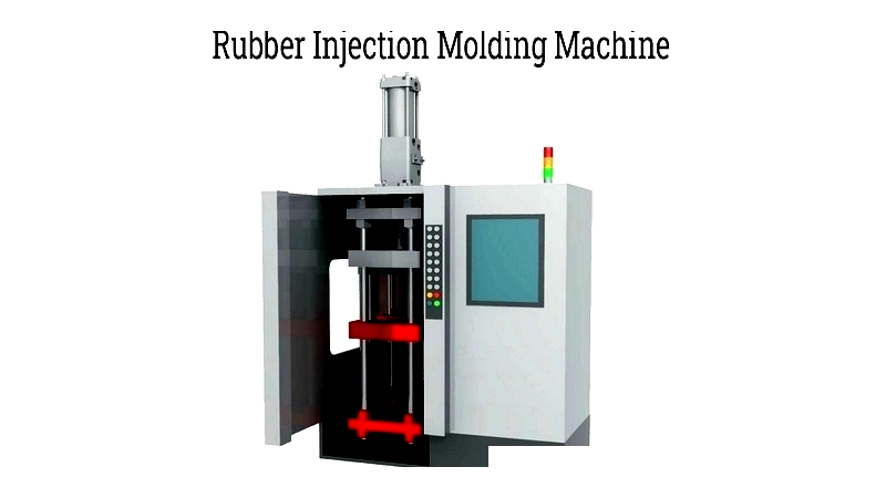
Rubber injection molding transforms raw rubber into finished products by injecting it into pre-formed metal molds. Pressure initiates chemical reactions like vulcanization, linking polymer chains within the material.
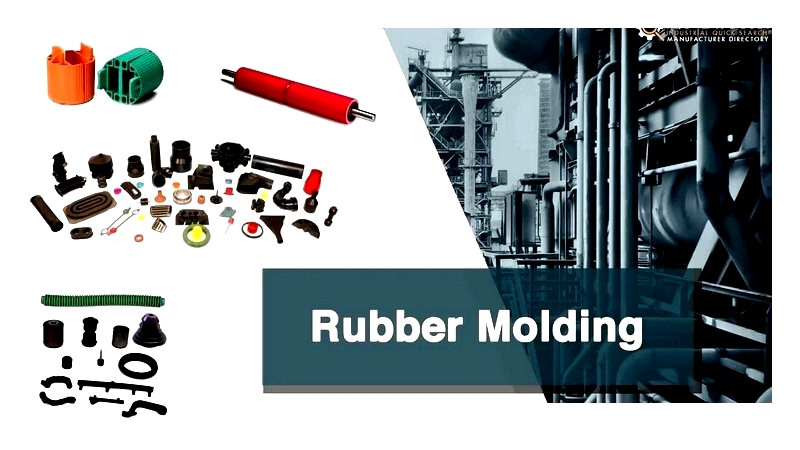
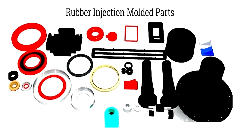
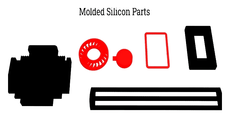
The process combines heat and pressure to create components like gaskets, hoses, and O-rings. Manufacturers continually innovate to meet evolving product demands.
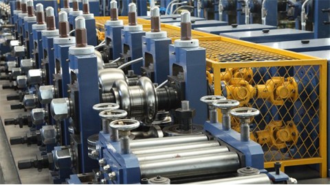
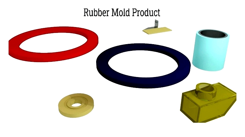
Rubber Mold Creation Process
This automated method replaces manual shaping, enabling chemical reactions that enhance rubber's toughness. Polymer chain interlinking allows stretch and recovery under stress, with heat accelerating curing for complex shapes.
Engineers optimize component geometry for cost efficiency, carefully positioning parting lines and draft angles. Mold design critically impacts production success.
Molds are crafted from durable metals like steel or aluminum using computer-aided technology for precision. Steel's longevity often justifies its higher initial cost.
Advanced methods reduce mold production time. Post-casting, molds undergo rigorous testing to verify dimensional accuracy.
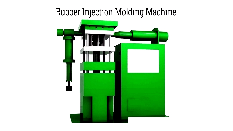
Injection Molding Process
This preferred method creates high-precision products. Raw rubber is heated to liquid form ("gum stock") for easy mold filling.
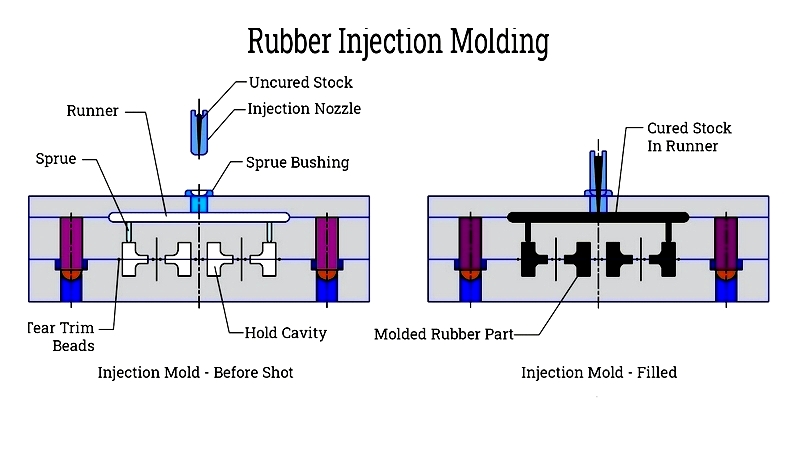
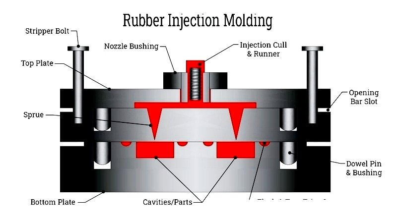
Preheating reduces curing time, enabling higher temperatures. Clamped molds prevent flashes, while barrel-nozzle systems ensure consistent material flow.
Rubber enters through runners and sprues, filling cavities precisely via gates to form the desired shape.
Chapter 2: Rubber Types and Processing Methods
This chapter details rubber compounds used in injection molding and explains production steps, helping manufacturers select optimal solutions for specific applications.
Common Rubber Materials
Various high-performance rubbers serve industrial, automotive, medical, and consumer applications:
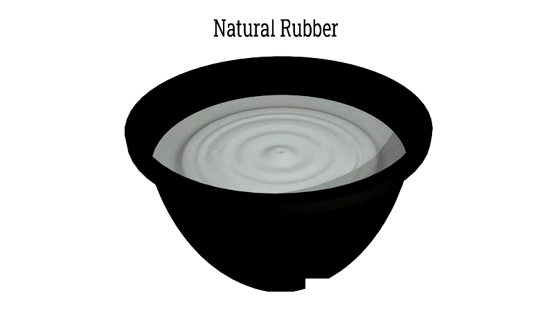
Natural Rubber
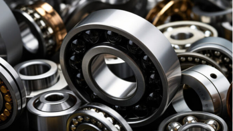
Sourced from latex, natural rubber offers excellent tensile strength and abrasion resistance, ideal for seals, O-rings, and dampers. Its metal-bonding capability makes it suitable for coatings.
Nitrile (Buna-N)
Synthesized from butadiene and acrylonitrile at 40°C, nitrile rubber resists oils, solvents, and abrasion, making it perfect for automotive seals and hydraulic components.
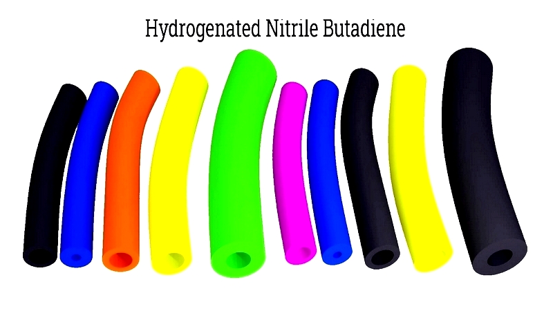
Hydrogenated Nitrile (HNBR)
HNBR's hydrogenation process enhances resistance to petroleum products, fuels, and extreme conditions, valuable in automotive powertrains.
EPDM Rubber
Ethylene propylene diene monomer resists light, ozone, and heat, serving well in automotive, construction, and electrical applications.
Silicone
Composed of silicon, oxygen, carbon, and hydrogen, silicone withstands extreme temperatures and is widely used in medical devices and weather-resistant products.
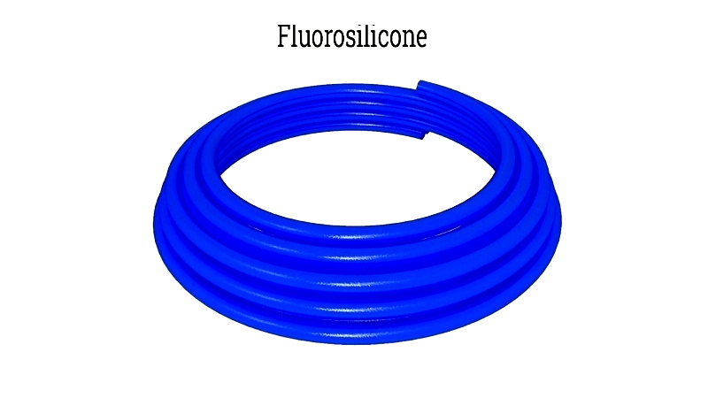
Fluorosilicone
This specialized silicone resists fuels and chemicals while maintaining flexibility, making it essential for aerospace applications.
Neoprene
Polychloroprene offers fire, weather, and temperature resistance for gaskets, hoses, and protective coatings across multiple industries.
Styrene-Butadiene
SBR rubber provides excellent aging and abrasion resistance for tires, footwear, and industrial components.
Fluorocarbon
Viton® fluororubbers withstand extreme temperatures and chemicals, ideal for fuel systems and harsh environments.
Butyl Rubber
This gas-impermeable material suits high-pressure seals and sound-dampening applications in pharmaceuticals and tires.
Urethane
Polyurethane offers exceptional abrasion resistance and load-bearing capacity for industrial components.
Thermoplastic Elastomers
TPEs combine plastic and rubber properties, offering recyclability and design flexibility for consumer goods and medical devices.
Thermoplastic Vulcanizates
TPVs blend polypropylene and EPDM, providing durable solutions for automotive seals and gaskets.
Material Selection Factors
Choosing rubber involves evaluating chemical compatibility, temperature range, mechanical properties, and regulatory requirements like FDA or medical certifications.
Molding Processes
Specialized techniques include:
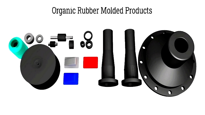
Organic Rubber Injection
This automated process reduces cycle times and improves consistency for high-volume production.
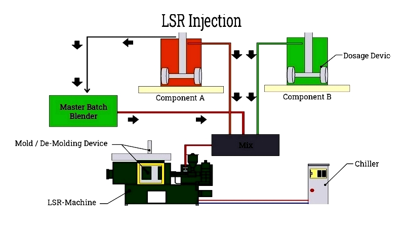
Liquid Silicone Molding
LSR injection offers contamination-free processing with rapid cycles, ideal for medical and electronic components.
Thermoplastic Rubber Injection
This plastic-like process enables color integration and quick turnarounds for consumer products.
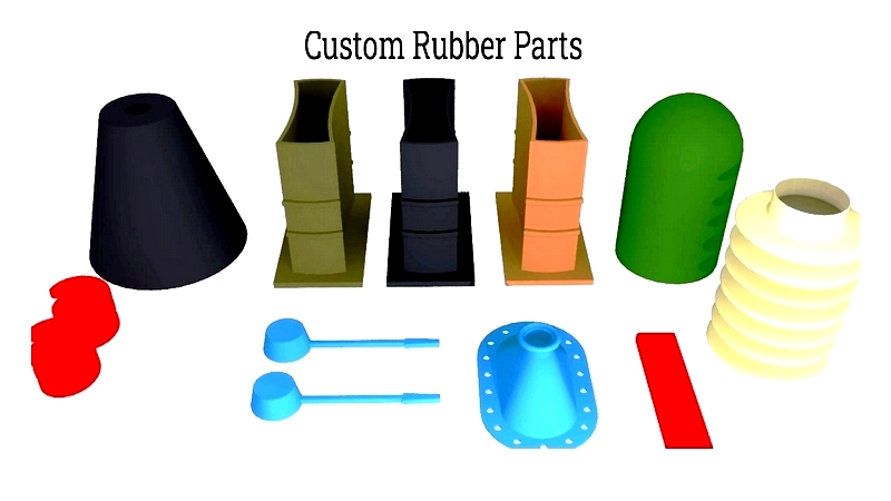
Custom Molding
Tailored solutions address unique component requirements through specialized engineering and prototyping.