Introduction
This article provides an in-depth examination of machine guards.
Key topics covered include:
- Principles of Machine Guards
- Types of Machine Guards
- Applications and Benefits of Machine Guards
- And More...
Chapter 1: Understanding the Principle of Machine Guards
This chapter examines the definition, design, and operational principles of machine guards, highlighting their critical role in workplace safety.
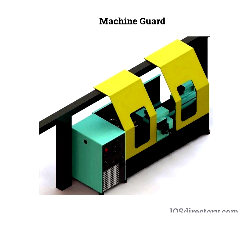
Defining Machine Guards
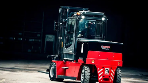
Machine guards are essential safety components designed to create a protective barrier between workers and machinery in environments like manufacturing plants and warehouses. These barriers also regulate vehicle access, control traffic flow, and contain debris. Nearly all machinery types require safety guards.
Machinery with potential hazards from impacts, rotations, shearing, or cutting tools requires appropriate guards to ensure operator safety.
Manufacturing Machine Guards
Manufacturers typically produce machine guards using CNC machining, extrusion, and post-extrusion techniques (employing rivets, bolts, nuts, screws, etc.). Further details on these methods follow.
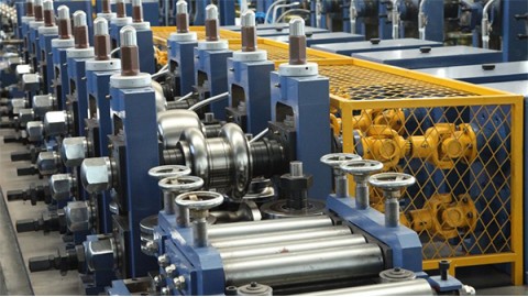
The Extrusion Process in Machine Guard Production
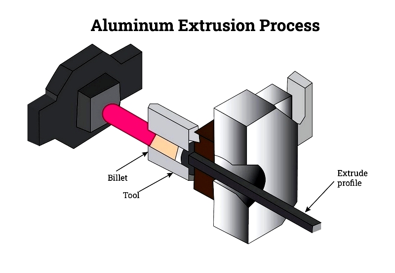
Extrusion shapes materials like aluminum by forcing them through a die with a specific opening, producing extended profiles matching the die's form. The process involves pushing aluminum through the die with a powerful ram, creating shapes that are pulled along a runout table. Basic aluminum extrusion is relatively straightforward to understand.
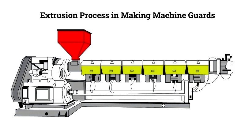
Extrusion yields three shape types: solid forms (angles, rods, beams), hollow forms (rectangular/square tubes), and semi-hollow shapes ("C" channels). These forms are crucial for machine guard production, as detailed in the following ten steps.
- Step One: Preparing and Positioning the Extrusion Die Machinists first create a circular H13 steel die. For optimal performance, the die is preheated to 450-500°C before being loaded into the press.
- Step Two: Preheating the Aluminum Billet Cylindrical billets cut from aluminum alloy logs are heated to 400-500°C, making them pliable but not molten.
- Step Three: Transferring the Billet to the Extrusion Press After preheating, billets are moved to the press and lubricated to prevent sticking.
- Step Four: Compressing the Billet with the Ram
The pliable billet enters the press, enduring up to 15,000 tons of pressure.
As pressure increases, the billet fills the extrusion container, constrained by its walls.
- Step Five: Extruded Material Emerges from the Die Under constant pressure, the alloy flows through the die opening, forming the desired profile.
- Step Six: Guiding and Quenching Extrusions The emerging extrusion is pulled onto the runout table and cooled uniformly with water or fans.
- Step Seven: Cutting Extrusions to Length once fully extended, a hot saw shears the extrusion from the process, with temperature control remaining critical.
- Step Eight: Cooling to Room Temperature After shearing, extrusions cool naturally on the table before stretching.
- Step Nine: Straightening Extrusions Profiles may twist during cooling and are straightened using a stretcher to meet specifications.
- Step Ten: Final Cutting to Size Straightened extrusions are cut to lengths of 8-21 feet, achieving T4 properties, with optional aging for T5/T6 properties.
- Post-extrusion, profiles may undergo heat treatment or surface finishing to enhance properties and appearance. Further fabrication can tailor dimensions to specific guard requirements.
Post-Extrusion in Machine Guard Manufacture
Post-extrusion shapes warm extruded sheets into forms, often during extrusion. This cost-effective method combines extrusion with injection molding benefits, commonly used with rigid PVC.
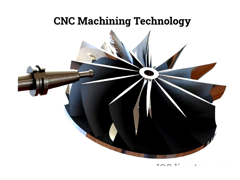
CNC Technology in Machine Guard Production
CNC machining uses advanced computer programs to autonomously design and produce precise parts, playing a foundational role in machine guard manufacturing. CNC (Computer Numerical Control) emphasizes computerized precision.
CNC encompasses various techniques for efficient, precise part production across different volumes.
Selecting a CNC Machine Shop
Choosing a CNC shop involves evaluating processes for guard production, considering dimensional capabilities, material suitability, production volume, software, and machinery types. Providers vary in materials and dimensions, with metals preferred for durability, though plastics are an alternative.
After selecting facilities and materials, the process begins with client-manufacturer collaboration. Using CAD/CAM and imaging software, designs are converted into machine code. Raw materials (metal/plastic billets) are loaded into machinery, either sourced by the shop or client.
In multi-machine setups, materials may be moved manually or automatically. The computerized system then executes commands to precisely create parts, enabling rapid, accurate duplication.
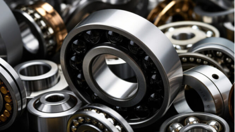
Materials for Machine Guards
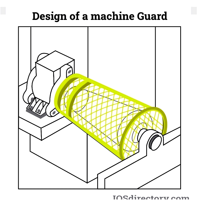
Machine guards are typically metal for strength and durability, formed into bars, pipes, mesh, or panels. Polycarbonate is used where visibility is needed, offering impact resistance. Wood suits low-temperature, non-corrosive environments.
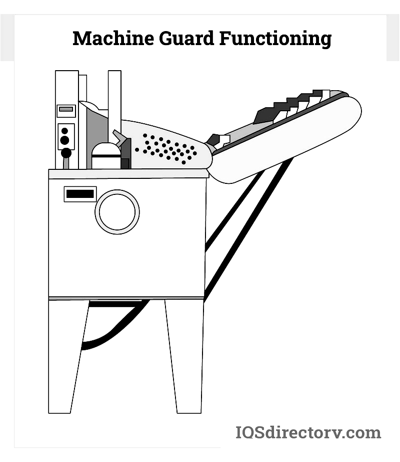
Functionality of Machine Guards
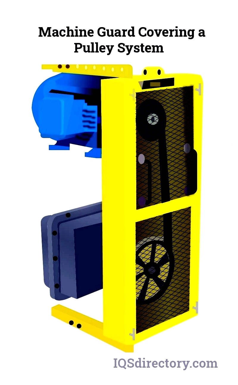
Industrial machine guards protect equipment through various methods, including point of operation guarding, point guarding, and fixed perimeter guarding.
Point guarding shields moving parts that endanger operators. Per OSHA 1910.212(a)(2), these guards must be securely attached or positioned nearby when direct attachment isn't feasible.
Point of operation guarding focuses on areas where operators interact with machines, preventing contact and maintaining safe zones.
Fixed perimeter guarding creates complete enclosures around machine workspaces, preventing unintended contact with moving parts.
Selecting Machine Guards: Key Considerations
important factors include:
Safety Regulations and Risk Assessment
Safety risks and regulations vary by workplace. evaluating conditions helps determine appropriate guard types (e.g., wire mesh vs. solid panels). Consult MSHA, OSHA, and CSA standards for specific machine risks.
Design and Manufacturing Insights
Basic knowledge of guard production aids in identifying quality standards, such as optimal wire gauges and weaving methods for mesh guards.
Custom Machine Guards
Custom guards may be needed when standard sizes don't fit. Wire mesh guards offer flexibility for unique machine configurations.
Customer Support
Choose manufacturers offering comprehensive guidance and post-sale support to address future inquiries or issues.
Chapter 2: Types of Machine Guards
Machine guards fall into four main categories: fixed, adjustable, <