Introduction
This comprehensive guide covers everything you need to know about work equipment platforms and their applications.
Key topics include:
- Work Equipment Platform Fundamentals
- Various Types of Work Equipment Platforms
- Practical Applications
- Construction and Design Features
- Selection Criteria
- Additional Essential Information
Chapter 1: Understanding Work Equipment Platforms
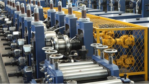
Work equipment platforms are elevated surfaces in manufacturing and production facilities that provide convenient access to machinery. These platforms improve operational efficiency by maximizing previously underutilized space. Built from durable materials like heavy-duty steel or aluminum, they withstand demanding worksite conditions.
Unlike standard floor space, equipment platforms aren't classified as structural areas and face fewer regulations than mezzanines. While mezzanines require fire safety systems like sprinklers, platforms with stairs or ladders are exempt from these requirements. They're ideal for businesses with limited floor space but available vertical space, improving both workspace and safety. Being independently constructed, they can be placed anywhere without building attachments. Clear terminology is essential when discussing platform installations.
Chapter 2: Work Equipment Platform Varieties
These essential components serve multiple industries including manufacturing, warehousing, and construction. Available in custom or modular designs, platform selection depends on intended use - from basic inspection surfaces to heavy-duty supports for large machinery. Their versatility stems from wide load capacities (50-250 PSF), making them suitable for diverse applications.
Safety Platforms
Engineered for worker protection, these platforms feature anti-slip surfaces, guardrails, and ladder access. Sizes range from inches to several feet, with some including staircases. Common in warehouses and factories, they're crucial for safe inventory access. Forklift-mounted versions require fall protection gear for elevated tasks.
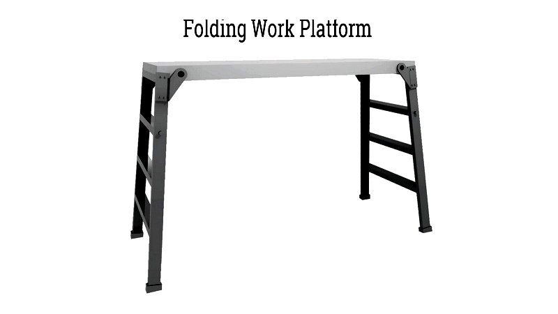
Folding Platforms
Popular among painters and contractors, these lightweight, portable platforms offer temporary elevated workspaces. Their locking legs and slip-resistant surfaces ensure stability and safety. Available in various dimensions, they're ideal for ceiling work, shelving access, and service tasks.
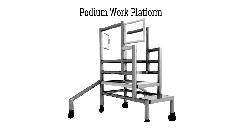
Podium Platforms
Combining ladder and stand features, these platforms offer superior fall protection with enclosed guardrails. Adjustable heights and collapsible designs make them versatile for lighting installation and maintenance work. Their durable construction suits demanding environments.
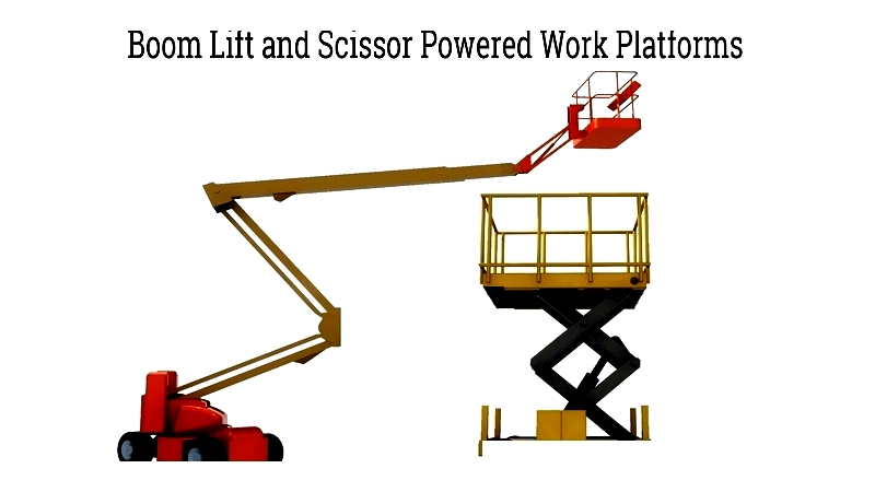
Powered Platforms
Including scissor lifts and boom lifts, these mobile or stationary units safely elevate workers. Essential for construction and maintenance, they improve efficiency while reducing fall risks. Types include:
- Boom Lifts: Hydraulic-arm platforms for extended reach
- Scissor Lifts: Stable vertical-lift platforms
- Vertical Lifts: Compact indoor solutions
- Articulated Booms: Multi-jointed for precise positioning
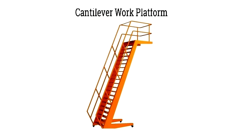
Cantilever Platforms
Adjustable platforms for vehicle and machinery access, these project workers over equipment without direct contact. Ideal for trucking and aviation maintenance, they typically reach 8-15 feet high.
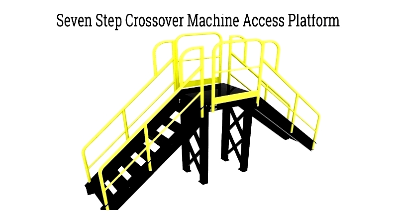
Machine Access Platforms
Custom-built for specific equipment, these platforms feature safety elements like anti-slip surfaces and compliant railings. Common in factories, they facilitate equipment monitoring and maintenance.
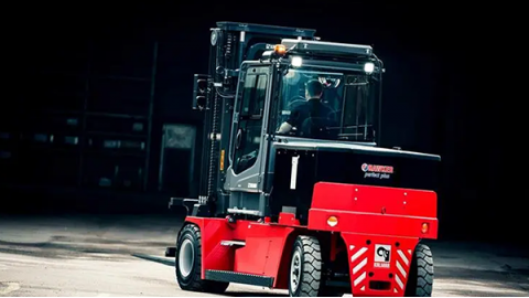
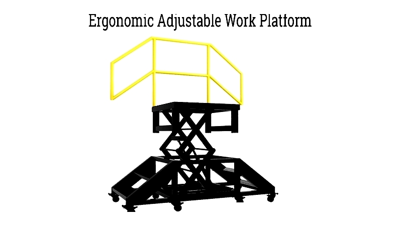
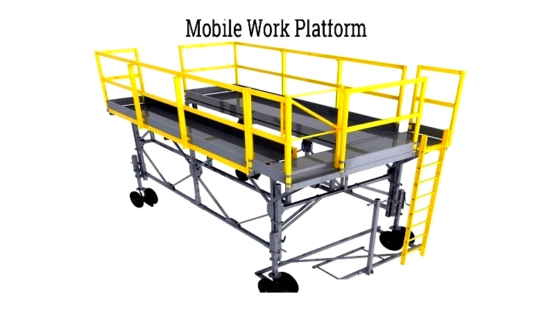
Mobile Platforms
Wheeled for flexibility, these platforms suit dynamic environments like warehouses. Their ergonomic designs boost productivity while maintaining safety. Advanced models offer powered movement and height adjustment.
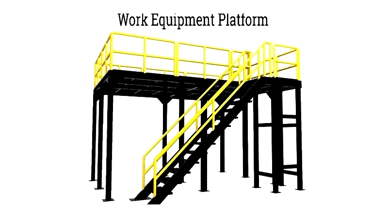
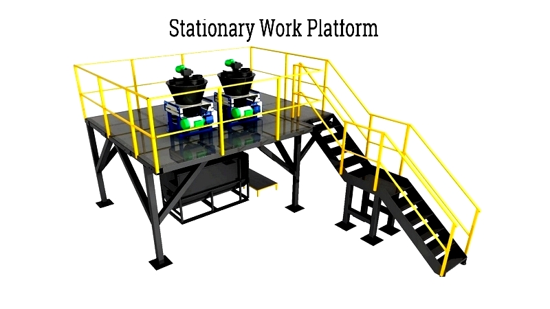
Stationary Platforms
Permanent installations for machinery servicing and assembly, these range from small stools to large equipment-surrounding structures. Typically 8-10 feet high, they optimize space while ensuring continuous access.
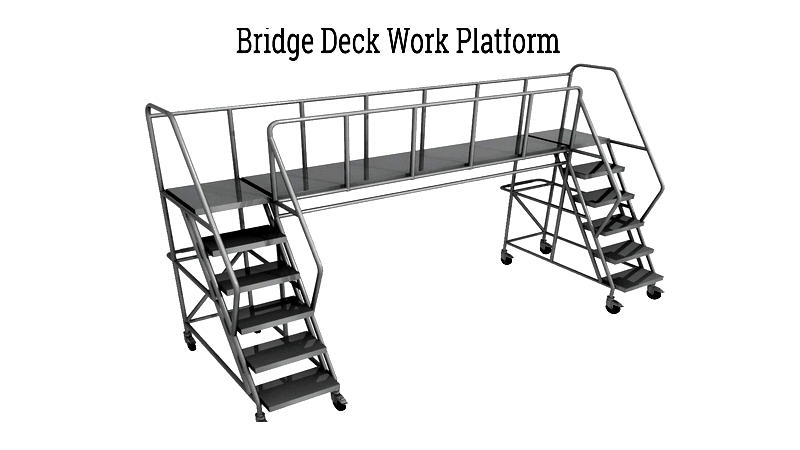
Bridge Deck Platforms
Combining portability and strength, these span-supported platforms enable multi-point access. Ideal for manufacturing and infrastructure projects, they allow quick repositioning.
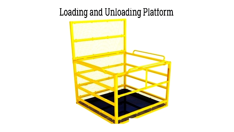
Loading Platforms
Designed for material handling, these platforms feature safety rails and reinforced decking. Available for indoor/outdoor use, they streamline vertical material transport.
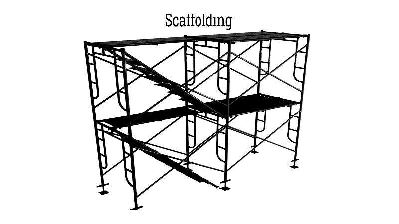
Scaffolding
Temporary structures for construction and maintenance, these modular systems support multi-level work. Compliance with safety standards is paramount.
When selecting platforms, consider use requirements, load capacity, environment, mobility, space constraints, and safety regulations. For complex material flow, integrate platforms with vertical conveyors. Choose certified suppliers for reliable, compliant solutions that ensure long-term safety and efficiency.
Chapter 3: Platform Applications
These versatile solutions optimize vertical space in commercial and industrial settings. Their customizable designs serve diverse industries, enhancing workflow and storage while ensuring safety and compliance. Essential for manufacturing plants, warehouses, and maintenance facilities, they boost productivity through adaptable configurations.
Access Solutions
Modern industrial operations require secure access to distributed components. Equipment platforms provide OSHA-compliant access points with integrated safety features, improving maintenance efficiency while minimizing risks.
Safety Compliance
OSHA standards mandate comprehensive safety measures for elevated work areas. Required protections include fall systems, secure railings, and clear walkways. Regular training and inspections maintain compliance and prevent accidents.
Aerospace Applications
Specialized platforms address unique aircraft maintenance challenges. Their adaptable designs accommodate various aircraft configurations, ensuring safe access for assembly and repair tasks.