Introduction
This article provides a comprehensive guide to planetary gears and their applications.
You will learn about:
- What planetary gears are
- How planetary gears are manufactured
- The various types of planetary gears
- And much more...

Chapter One: What is a Planetary Gear?
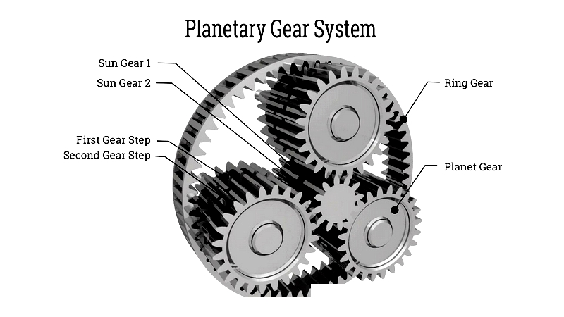
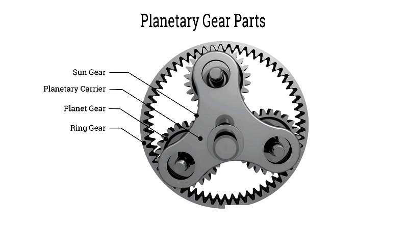
A planetary gear set, also called an epicyclic gear system, consists of a central sun gear that serves as the input. Three or more planet gears revolve around this central gear, engaging with an outer ring gear that features internal spur gear teeth. This unique arrangement enhances the system's durability and adaptability to various gear ratios.
As efficient speed reducers, planetary gears are widely used in automotive transmissions, wheel drives, and industrial conveyors. Their compact design, high ratio capability, and robustness make them ideal for diverse applications. The system's resilience comes from even load distribution among the sun and planet gears, enabling higher torque capacity and greater reduction through multiple gear contact points.
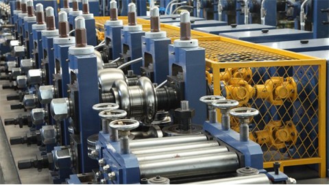
Chapter Two: How Planetary Gears are Made
Planetary gear sets, also known as epicyclic gear trains, are precision mechanisms that convert reciprocating motion into rotary motion. First developed by William Murdoch in 1781 as a steam engine improvement, modern planetary gears provide significant speed reduction and torque multiplication in compact spaces. They're essential components in automotive transmissions, industrial machinery, EVs, wind turbines, and robotics.
The core components include a sun gear, multiple planet gears, a ring gear, and a planet carrier. This arrangement ensures stability through even mass distribution and rotational stiffness, creating a durable, compact system. In planetary gearboxes, torque is applied radially and transmitted efficiently without excessive tooth pressure, improving mechanical efficiency and longevity.
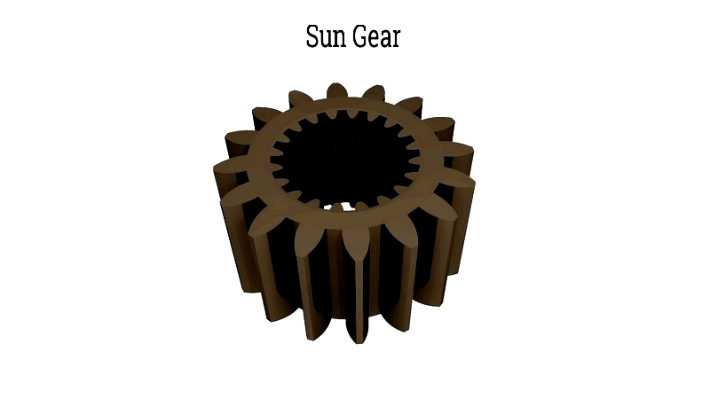
Sun Gear
The central sun gear receives input from the power source and drives the surrounding planet gears. These planet gears then transmit motion to the ring gear. By fixing different components (sun, ring, or carrier), planetary gears can achieve multiple ratios for both high and low-speed operations in a single unit.
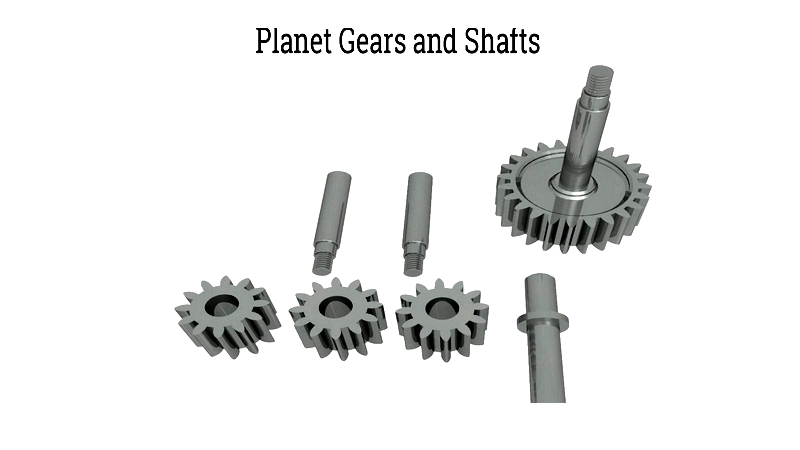
Planet Gears
Mounted on a carrier, planet gears rotate while revolving around the sun gear. Their continuous meshing with the ring gear distributes load across multiple contact points, reducing vibration and increasing torque capacity. Systems typically use three or more planet gears for heavy-duty applications like automatic transmissions and industrial reducers.
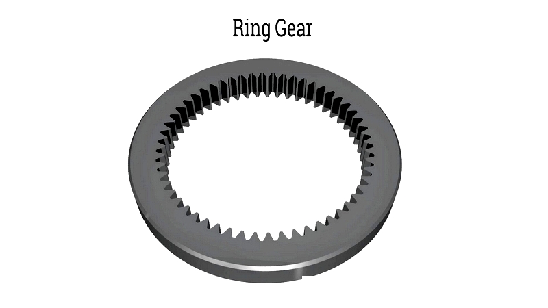
Ring Gear
The outer ring gear has internal teeth that mesh with the planet gears. While often fixed, it can serve as input or output in some configurations. As planet gears orbit the sun gear, they drive the ring gear in the same or opposite direction, depending on design requirements.
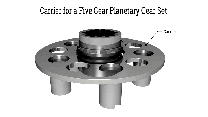
Carrier
The carrier supports and aligns the planet gears with the sun gear for smooth rotation. Simple systems use one carrier, while compound systems employ multiple carriers to increase gear ratios and power density for demanding applications like heavy machinery.
Planetary Gear Construction
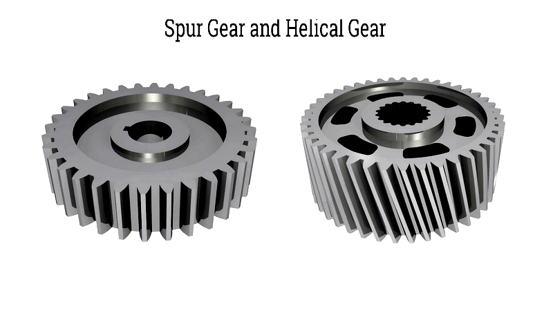
Planetary gears combine multiple inputs to achieve specific outputs. The sun gear meshes directly with planet gears mounted on a high-strength carrier. Systems may use spur gears for simplicity or helical gears for smoother, quieter operation with higher load capacity.
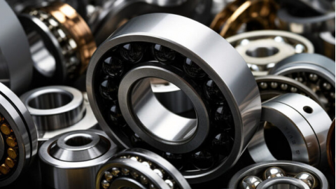
Bearings are crucial for torque transmission and lifespan. Tapered roller bearings handle both radial and axial loads, while advanced systems may use ceramic bearings for demanding environments. Modern planetary gears serve diverse industries, from automotive to aerospace, with custom solutions available for specific requirements.
Chapter Three: Types of Planetary Gears
Planetary gear systems offer versatile performance in power transmission. While complex to design, their compact size, high torque output, and minimal noise make them ideal for various applications from robotics to industrial gearboxes.
Common planetary gear types include:
- Single-stage planetary gear sets
- Multi-stage planetary gear trains
- In-line planetary reducers
- Offset planetary systems
- Coaxial planetary gearboxes
- Right-angle planetary drives
- Harmonic drives
- Differential planetary sets
- Simpson compound sets
- Ravigneaux assemblies
Specialty configurations exist for demanding applications in aerospace, automotive, and precision industries.
Single-Stage Planetary Gear Set
The basic design features a sun gear, planet gears, carrier, and ring gear. Ideal for space-constrained applications, they balance compact size with high torque density in machinery and transmissions.
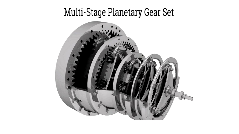
Multi-Stage Planetary Gear Set
Multiple stages in series provide higher reduction ratios and torque capacity while maintaining compactness. Common in wind turbines and heavy industrial applications.
In-Line Planetary Gear Set
Coaxial input/output shafts deliver efficient power transmission with minimal backlash, ideal for servo drives and automation equipment.
Offset Planetary Gear Sets
Parallel but non-colinear shafts suit space-limited applications like printing presses with unique orientation requirements.
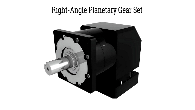
Right-Angle Planetary Gear Sets
90-degree shaft configurations save space in conveyor drives and machine tools through bevel or hypoid gear integration.
Harmonic Drive Planetary Gear Set
Using flexible components, these achieve ultra-high reduction ratios with near-zero backlash for precision robotics and CNC machinery.
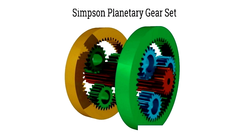
Simpson Planetary Gear Set
This compound system offers multiple gear ratios, making it standard in traditional automatic transmissions for its reliability and compact design.
Ravigneaux Planetary Gear Set
Featuring two sun gears and planet sets on one carrier, it provides more ratios in lighter packages for modern transmissions.
Differential Planetary Gear Set
Essential for vehicles, these allow wheels to spin at