Introduction
This article provides an in-depth exploration of modular buildings.
Continue reading to learn more about:
- What modular buildings are
- The different types of modular buildings
- Their advantages and disadvantages
- Industries that utilize modular buildings
- And much more
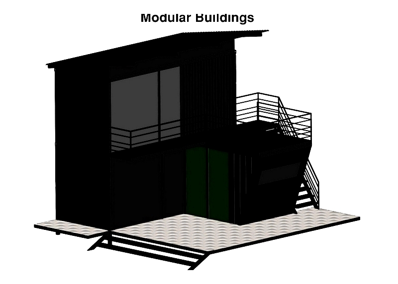
Chapter 1: What are Modular Buildings?
Modular buildings consist of standardized components called "modules," manufactured in controlled factory environments rather than on construction sites. These factory-built modules typically include walls, doors, ceilings, frames, and windows. They use the same materials and comply with the same building codes as conventional structures. once completed, these modules are transported to the construction site and assembled according to specific design requirements.
Modular construction is known for its speed, often completing projects in half the time of traditional methods. Despite the accelerated timeline, modular buildings maintain structural integrity. Specialized manufacturers offer extensive expertise to meet client needs, whether for permanent or relocatable structures. Their advanced manufacturing processes and strict quality controls ensure these buildings meet or exceed industry standards.
Chapter 2: Types of Modular Buildings
Building Systems
The modular construction industry primarily consists of two specialized segments: permanent modular constructions (PMC) and temporary modular constructions (TMC). Each system addresses unique architectural and operational needs, contributing to modular construction's growing popularity. Offsite fabrication and precision engineering reduce onsite labor and construction timelines while improving cost efficiency and quality control.
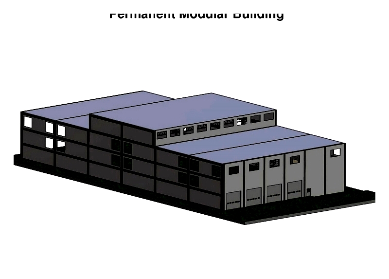
Permanent Modular Construction
Permanent modular construction (PMC) creates facilities designed for long-term use at their assembled location. Using offsite manufacturing techniques, building sections are prefabricated in controlled environments to ensure quality and structural integrity. Unlike conventional buildings, PMC structures remain permanently in place.
PMC buildings use permanent concrete foundations and can function independently or integrate with existing structures. Constructed with durable materials like galvanized steel and reinforced concrete, they offer design flexibility and customization options including lobbies, elevators, and energy-efficient systems. This approach suits multi-story commercial buildings, schools, healthcare facilities, offices, and residential spaces. Assembly time varies based on size, complexity, and code requirements.
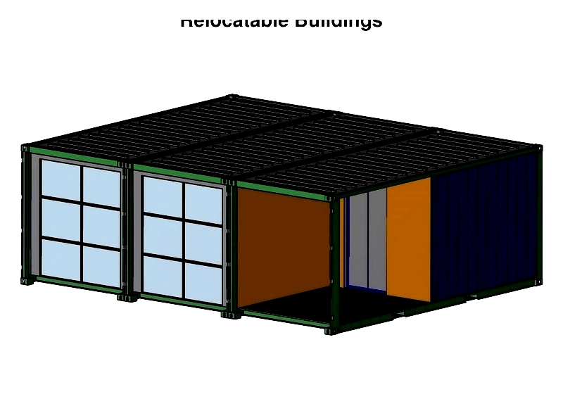
Temporary Modular Construction (Relocatable Buildings)
Temporary modular construction (TMC), or relocatable buildings, creates facilities for short-term or changing locations. Designed for easy disassembly and transportation, these buildings maintain compliance with safety standards while sharing PMC's fabrication techniques.
TMC structures serve applications requiring rapid occupancy, including disaster relief, temporary clinics, classrooms, and retail spaces. Made from lightweight yet durable materials, they're available for lease or purchase. While customization options are more limited than PMC, modern manufacturing still allows for tailored layouts and utility integration.
The following are the main types of modular buildings used across industries:
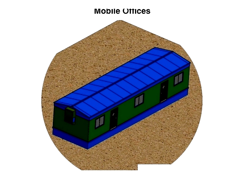
Mobile Offices
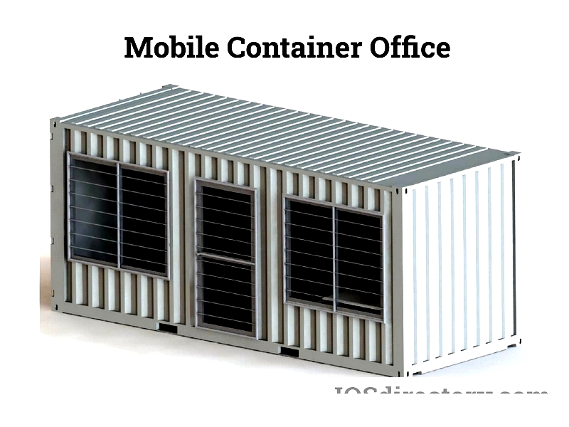
Mobile offices are portable workspaces with mobility features, offering traditional office functionality at job sites. Equipped with modern furniture, electrical infrastructure, and climate control, they provide flexible solutions for temporary needs. Easily transported, they're cost-effective for construction contractors, event organizers, and remote teams requiring professional, relocatable workspaces.
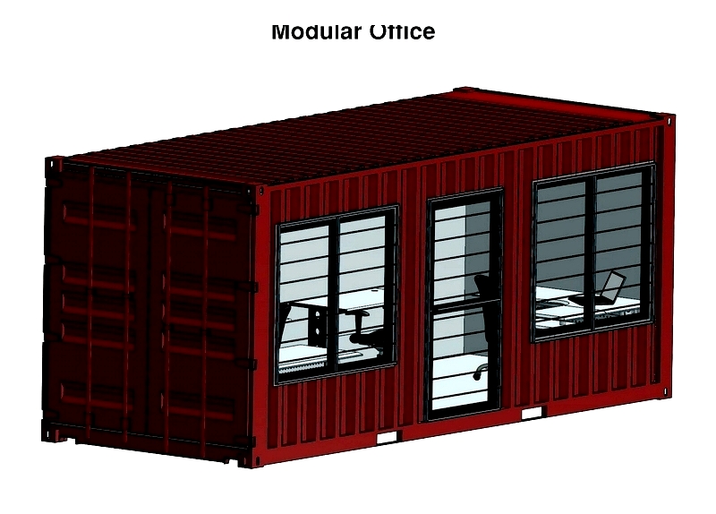
Modular Offices
Modular offices are factory-built facilities providing scalable space solutions within existing structures. Quickly assembled without disrupting operations, they're ideal for team expansion and project supervision. Their configurable design allows for room additions and reconfiguration as needs evolve, optimizing space utilization during facility transitions.
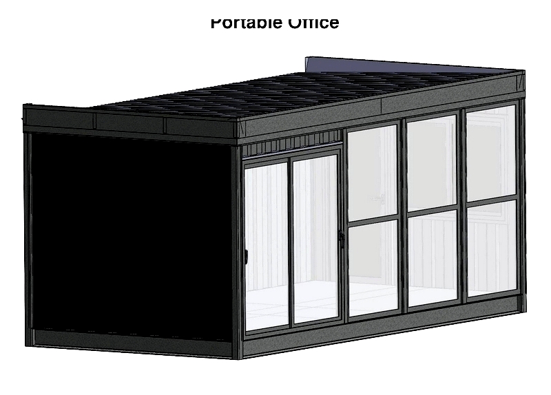
Portable Offices
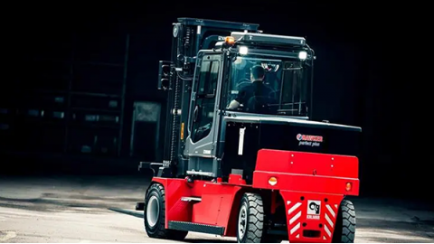
Portable offices are prefabricated buildings on transportable bases, easily relocated by forklift or truck. Ideal for temporary needs like construction sites or field offices, they provide comfortable environments for various operations.
Prefabricated Booths
Prefabricated booths are compact, self-contained structures manufactured offsite for quick assembly. Featuring customizable elements like HVAC and electrical systems, they ensure occupant comfort while enabling rapid installation and code compliance.
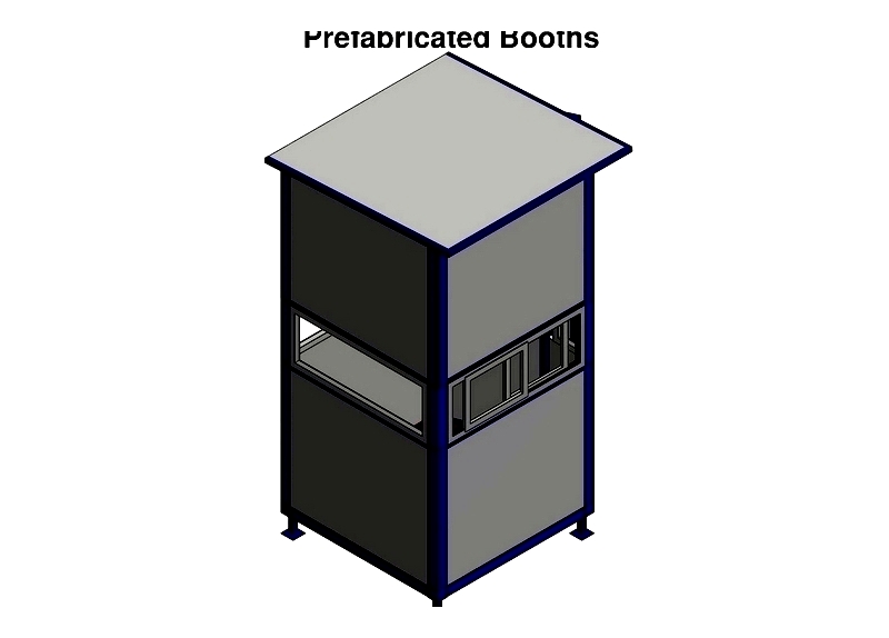
Available as permanent or temporary installations, these booths serve diverse applications:
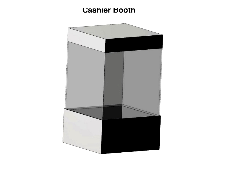
Cashier Booths
Cashier booths are secure modular units for commercial settings, featuring transaction windows and reinforced doors. Their security features protect assets in high-traffic environments while streamlining customer service.
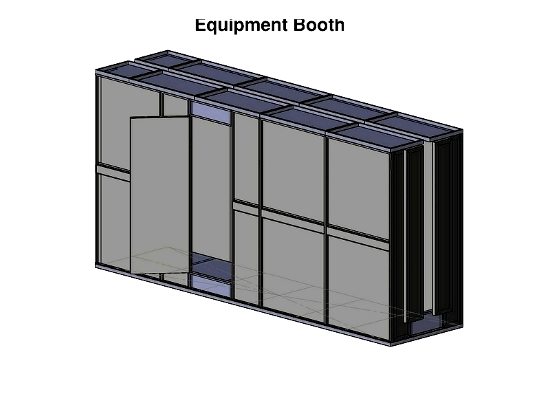
Equipment Booths
Equipment booths protect sensitive machinery from environmental factors, extending equipment lifespan and reducing maintenance costs in industrial settings.
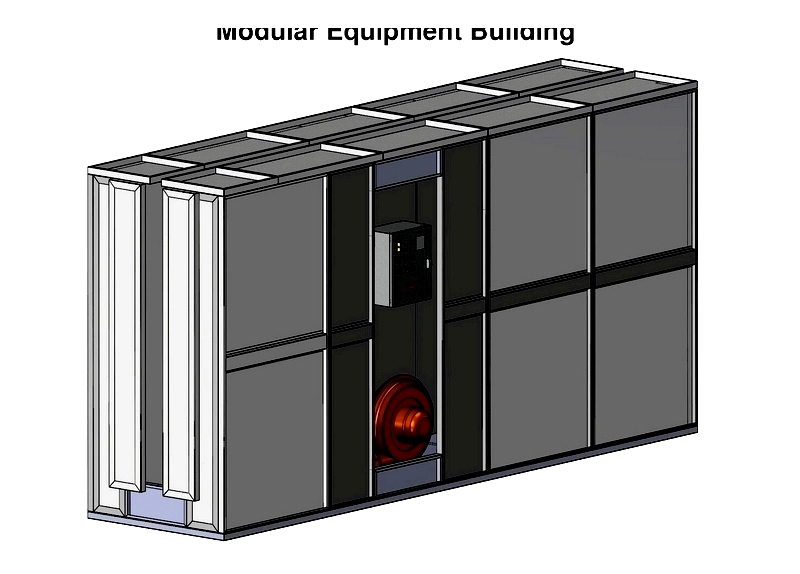
Modular Equipment Buildings
Larger versions of equipment booths, these buildings house industrial systems with features like sound attenuation and fire suppression, meeting strict safety standards for critical infrastructure.
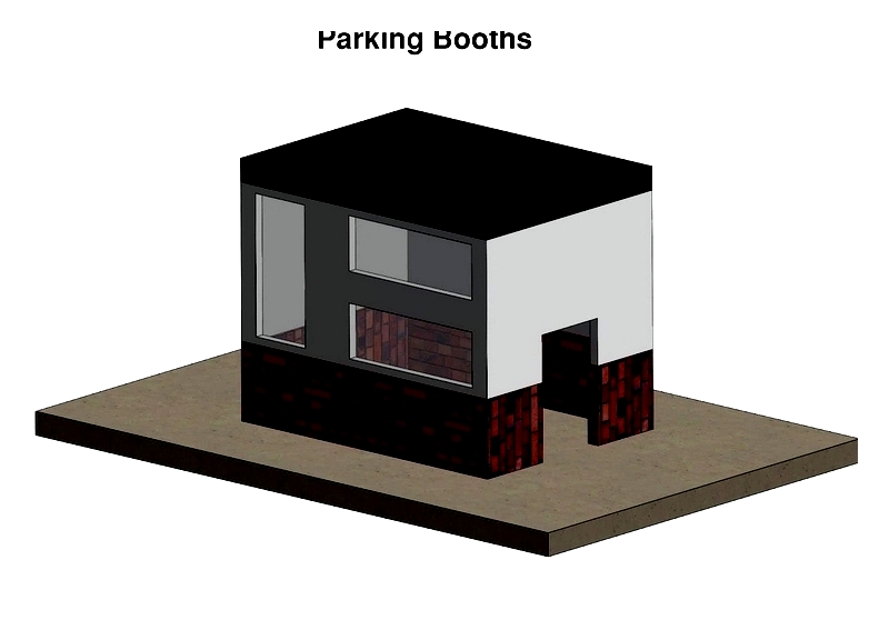
Parking Booths
Parking booths manage vehicle access at parking facilities, incorporating modern technologies like cloud-based systems and surveillance cameras to enhance security and efficiency.
Prefabricated Shelters
These rapidly deployable enclosures provide protection from harsh conditions, customizable with heating, lighting, and power solutions for various applications including disaster response and public venues.
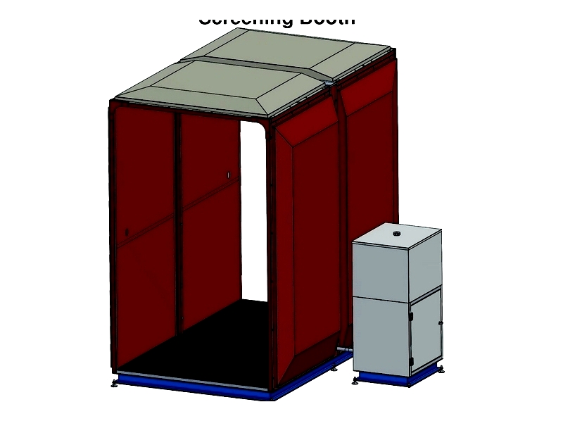
Screening Booths
Popularized during the pandemic, these booths facilitate health screenings with features like contactless scanners and negative airflow systems, adaptable to changing operational needs.
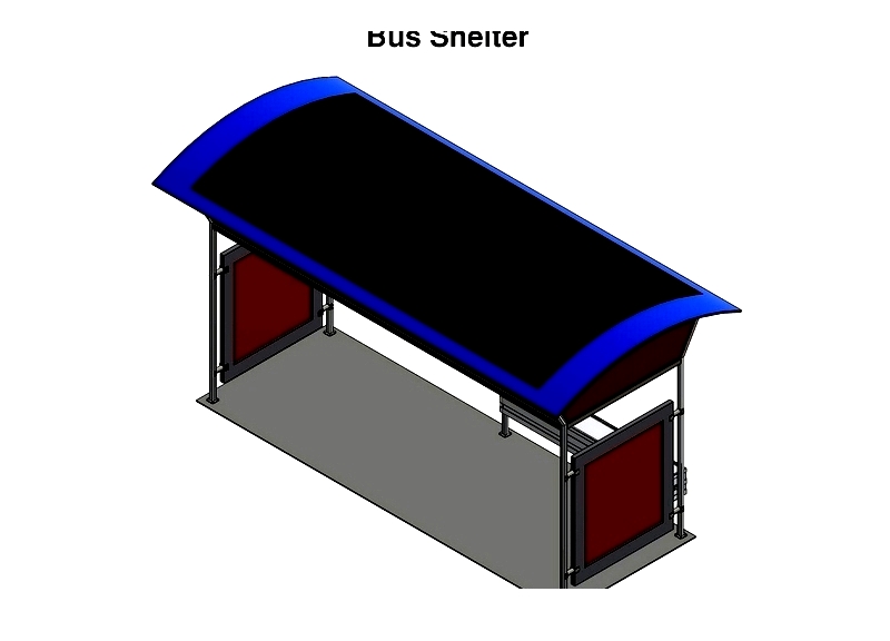
Bus Shelters
Protecting commuters from weather elements, these durable structures may include seating, transit information displays, and solar panels to enhance public transit infrastructure.
Guard Houses
Strategically placed security enclosures feature reinforced construction and surveillance systems for effective site monitoring at various facilities.