Introduction
This article provides an in-depth exploration of plastic baggies.
You'll discover information on various topics including:
- What Plastic Baggies Are
- The Manufacturing Process of Plastic Baggies
- Types of Plastics Used for Plastic Baggies
- Common Uses of Plastic Baggies
- And much more...
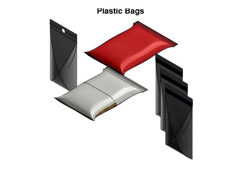
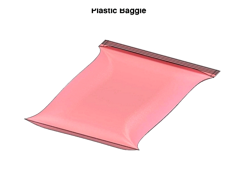
Chapter One – What is a Plastic Baggie?
A plastic baggie is a flexible pouch made from polymer materials. These containers are widely used for storing food, electronics, and pharmaceuticals, as well as in shipping and retail applications. Their practicality has made them essential in various settings.
Plastic baggies gained popularity because of their flexibility, affordability, and recyclability. Although plastics were used industrially since World War II, their widespread adoption began in the 1960s after being introduced by a Swedish engineer.
Lightweight yet durable, plastic baggies are ideal for carrying items like groceries, which contributed to their rapid acceptance. While initially considered environmentally harmful, improved recycling technologies and increased public awareness have led to more responsible usage and disposal practices.
Beyond industrial uses, plastic baggies are common in households for storage. Standard sizes range from one quart to a gallon, with compact versions for daily use and larger options for industrial needs.
Chapter Two – How Plastic Baggies Are Made
Plastic baggies, also called resealable or poly bags, are manufactured using advanced polymer processing techniques. Typically made from a single plastic polymer like polyethylene, they combine durability with simplicity. The production process begins with selecting high-quality raw materials that meet specific requirements for flexible packaging.
Polymers used in baggie production come from petrochemicals in granular or pellet form. During polymerization, additives like color pigments or UV-resistant compounds can be included to enhance performance. Understanding the polymer's composition is crucial for meeting safety and environmental standards, especially for food-grade packaging.
Plastic Bag Creation Process
Polymer Selection
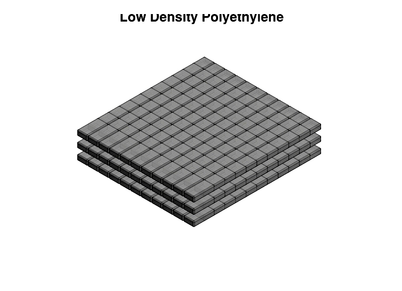
Choosing the right polymer is critical for determining strength, flexibility, and sustainability. Manufacturers mainly use polyethylene variants—HDPE, MDPE, LDPE, and LLDPE—each suited for different applications like food storage or industrial packaging.
Polyethylene is the industry standard due to its chemical resistance, durability, and lightweight properties. Its customizable structure allows for various bag types, from heavy-duty industrial bags to airtight zip-lock versions. Polyethylene is synthesized through ethylene monomer polymerization, creating molecular chains that can be tailored for specific needs. Recycled polyethylene options are also available for eco-conscious businesses.
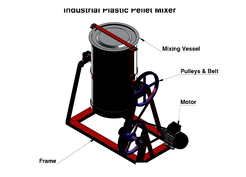
Polyethylene Mixing
The selected polyethylene resin is blended with LDPE or LLDPE in industrial mixers to create a uniform material. The mixing process varies based on the bag's intended use, such as freezer storage or static-sensitive electronics packaging. Proper mixer selection ensures consistent film thickness during production.
Melting the Resin
The blended resin is heated to a molten state (350°F to 410°F) for film formation. Precise temperature control prevents degradation, ensuring high-quality, food-safe, or medical-grade baggies.
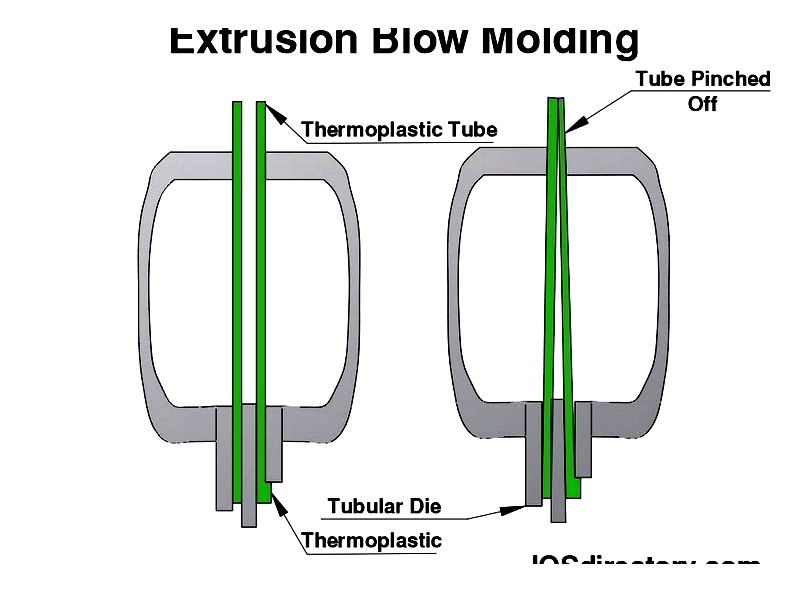
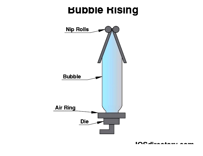
Extrusion Process
The molten resin is forced through an extruder and die, forming a "bubble" in the blown film extrusion process. Adjusting airflow and die gap controls thickness and strength, whether for sandwich bags or heavy-duty liners. The bubble is then stretched to the desired dimensions.
Cooling
The extruded film is cooled using air rings or water baths, solidifying its structure. Cooling rates can be adjusted for specialty bags like anti-static or moisture-resistant versions.
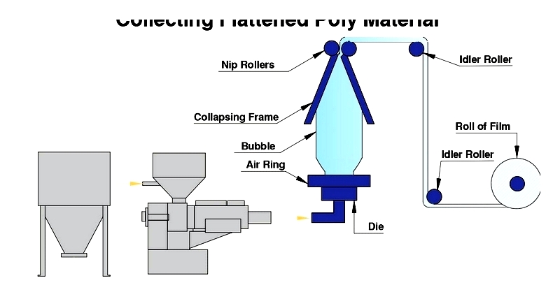
Flattening
The bubble is flattened into double-layered sheets, which are wound onto reels. Each roll can produce over 30,000 standard bags, making this method highly efficient. The flattened film is then ready for cutting and sealing.
Conversion
Film rolls are cut, formed, and sealed into finished bags. Additional features like gussets, handles, or zippers can be added. Custom printing is done using flexographic or gravure presses, with options for matte/gloss coatings or RFID tagging.
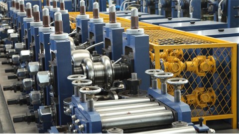
Specialty Bag Machines
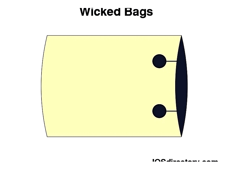
Wicket Bags
Wicket bags are designed for high-speed dispensing, held together by a metal rod. Ideal for food and medical industries, they offer customizable sizes and resealable options.
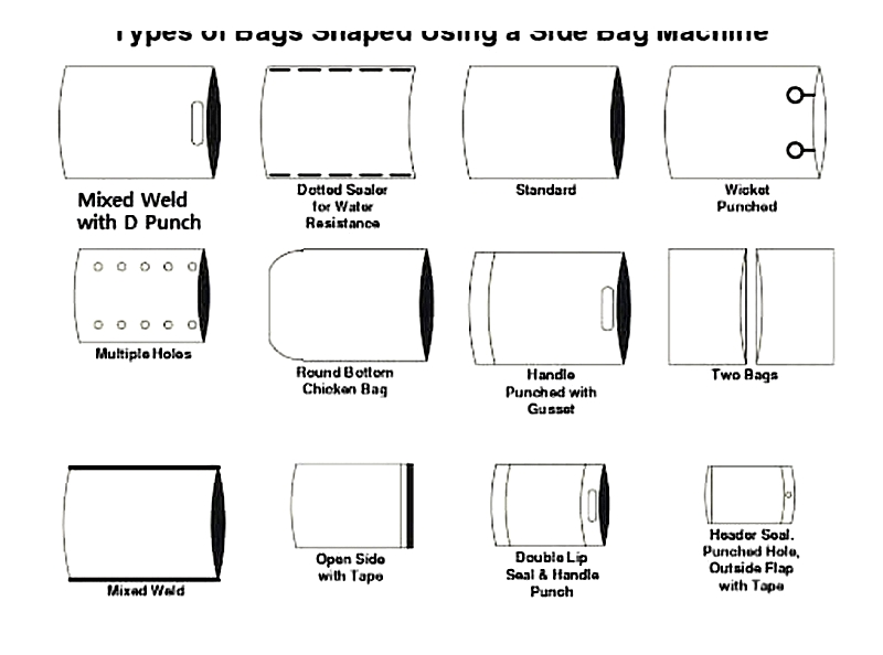
Side Sealing Machines
These machines produce various bag types with heat-sealed edges. Modular attachments enable features like handles or tamper-evident tape, useful for courier or merchandise bags.
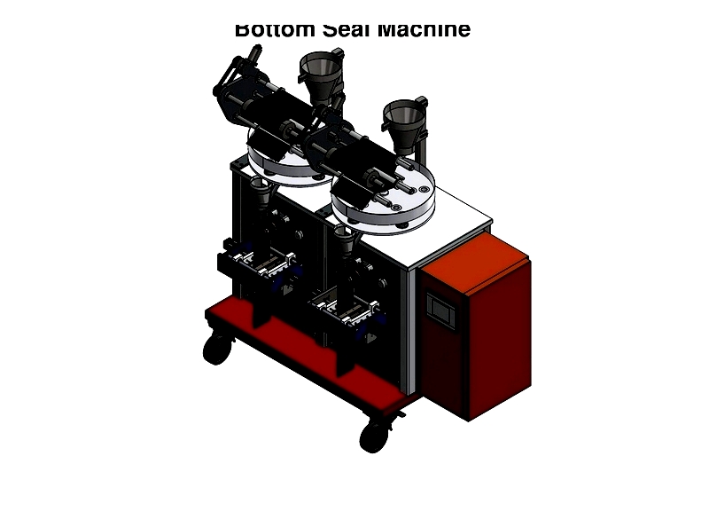
Bottom Seal Machines
Automating cutting and sealing, these machines produce trash bags and grocery sacks with uniform strength. They can process recycled materials for eco-friendly packaging.
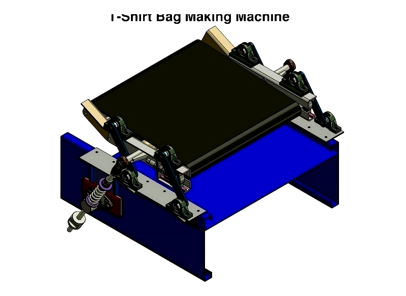
T-Shirt Bag Machines
These machines create retail shopping bags with handles, using HDPE, LDPE, or recycled blends. Precise controls ensure proper logo alignment for branding.
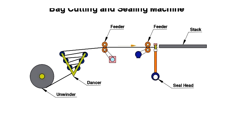
Bag Cutting
Automated cutting machines ensure precision and efficiency, handling various film types including biodegradable plastics. Quality checks guarantee compliance with industry standards.