Introduction
This article provides an in-depth exploration of hard cases and their applications.
You'll discover key topics including:
- What defines a Hard Case?
- Common Applications of Hard Cases
- Materials Used in Hard Case Construction
- Manufacturing Processes for Hard Cases
- Essential Hard Case Accessories
- And Much More...
Chapter One – Understanding Hard Cases
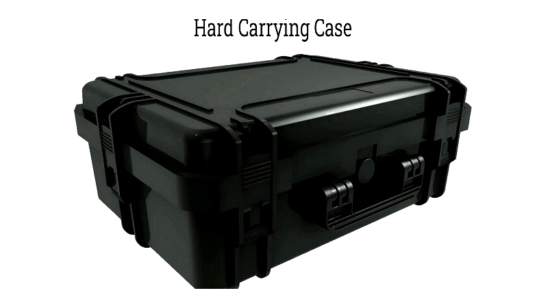
A hard case represents a durable carrying solution meticulously crafted from materials like molded plastic, aluminum, laminated wood, or various metals. These cases are specifically engineered to deliver superior security and robustness, featuring advanced protective elements and available in multiple sizes to accommodate diverse items. Many models include wheels for convenient transport, with dimensions ranging from compact units to larger versions spanning several feet in width and height.
Historically, hard cases were the preferred choice due to their exceptional ability to withstand harsh conditions, stress, and potential damage. While soft-sided cases gained popularity with new material innovations, hard cases maintain their essential role thanks to unmatched protection and longevity in carrying case design.
Chapter Two – Applications of Hard Cases
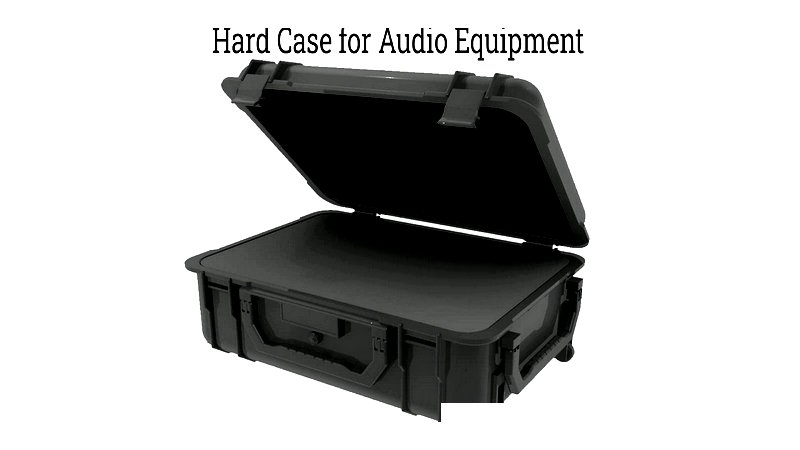
The standard hard case, typically resembling a large briefcase, remains fundamental for safely transporting and storing valuable equipment, tools, sensitive instruments, and medical devices. Designed for durability and security, these rugged cases serve critical functions across industries including aviation, military, law enforcement, medical, electronics, and audio/visual sectors. Most incorporate organizational features like customizable foam inserts and compartment dividers for efficient item management. While commonly associated with business briefcases, their applications extend to transportation, industrial operations, and specialty shipping needs where protection against impact, water, dust, and temperature variations is crucial.
Hard cases offer versatile transport solutions for diverse items ranging from complete sound and camera systems to firearms, scientific equipment, and drone technology. Evolving technology and user needs have driven case design innovations, with materials like rotationally-molded plastics and lightweight aluminum enabling specialty cases with enhanced protective features. Today's hard cases come in various sizes and protective ratings, providing custom solutions for unique transport and storage challenges faced by professionals globally.
Hard Case Applications
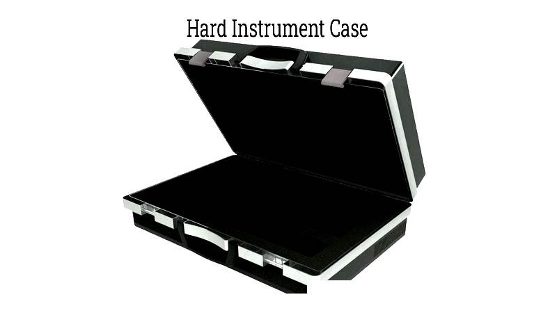
Instrument Cases
Instrument cases protect sensitive electronic instruments, laboratory tools, and precision optical equipment from shock, vibration, dust, and moisture. Made from high-quality materials like high-density polyethylene and aluminum alloys, these cases often feature environmental sealing and rugged exteriors. Interior foam inserts are precisely cut or molded to device dimensions for optimal impact absorption.
Understanding that minor impacts can affect instrument performance, these cases meet IP and MIL-STD-810 standards for harsh environments. Typically rectangular with secure latches and reinforced hinges, they offer portability and theft protection. Optional features include pressure relief valves, waterproof gaskets, and anti-static linings for electronics.
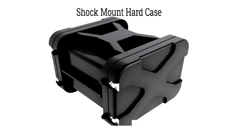
Shock Mount Cases
Shock mount cases feature internal suspension systems or shock-absorbing inserts to cushion impacts during transit. Using floating frames separated by high-density foam or rubber mounts, they protect sensitive electronics and military hardware from vibration and drops. Most offer IP67/IP68 ratings against water and dust, ensuring security during freight and field use.
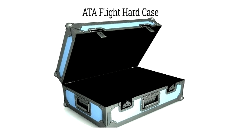
American Transportation Association (ATA) Cases
ATA cases meet strict air transport standards for audio/visual, broadcast, and medical equipment. Constructed from certified materials like ABS plastic and aluminum, they feature reinforced plywood walls and protective corner reinforcements. Spring-loaded latches and piano hinges ensure durability, while customizable foam interiors provide shock absorption. Compliance with ATA Standard 300 guarantees air travel protection.
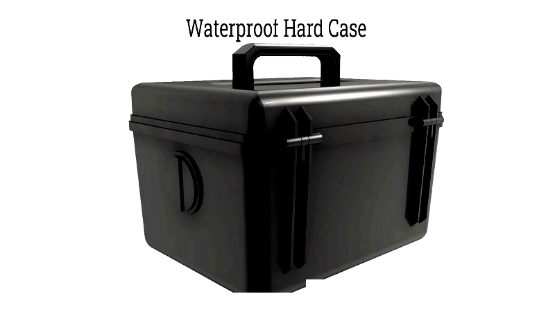
Waterproof Cases
Waterproof cases offer complete protection against water and contaminants for marine and outdoor applications. Meeting IP67/IP68 standards, they're made from impact-resistant polymers with corrosion-resistant hardware. Integrated seals and pressure valves ensure performance in harsh conditions, making them ideal for camera equipment and tactical gear.
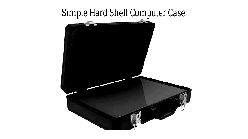
Computer Cases
Hard computer cases protect laptops and mobile workstations during travel and field use. Featuring shock-resistant linings and secure latches, many models include EMC shielding and air travel compliance. Custom-molded options provide snug protection for specialized IT equipment while maintaining accessibility.
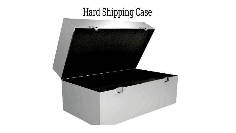
Shipping Cases
Shipping cases safeguard goods during commercial transport, meeting ATA and MIL-STD standards. With shock-absorbing construction and reinforced exteriors, they often include pressure valves and humidity control for international shipping. Customizable foam interiors and static shielding options accommodate specialized industrial needs.
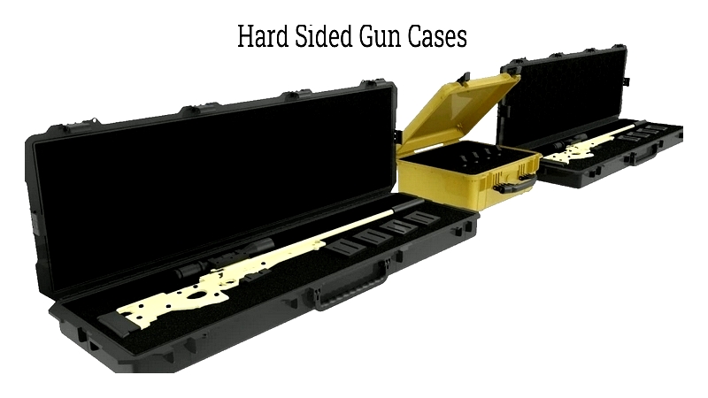
Gun Cases
Gun cases securely transport firearms and accessories, meeting regulatory requirements for shooting sports and law enforcement. Impact-resistant with foam padding and integrated locks, they're available in various sizes with TSA-approved options for air travel.
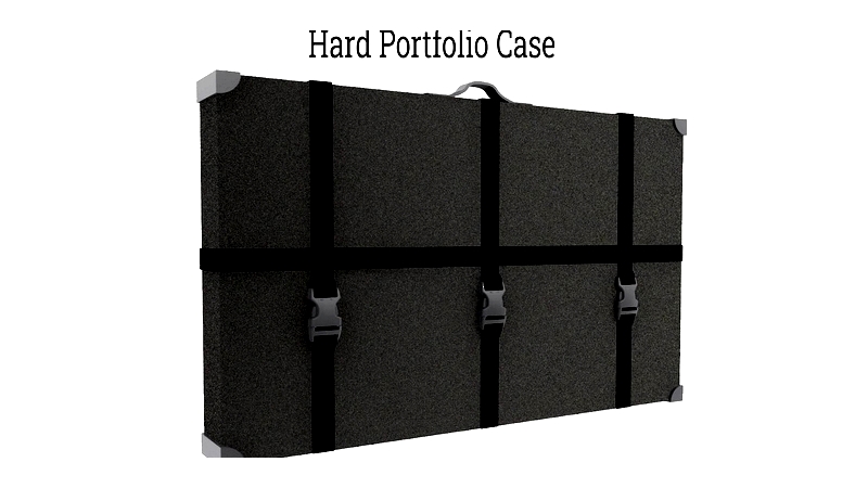
Portfolio Cases
Portfolio cases protect artwork and architectural plans with rugged shells and locking mechanisms. Water-resistant seals and adjustable compartments ensure professional presentation at exhibits and meetings.
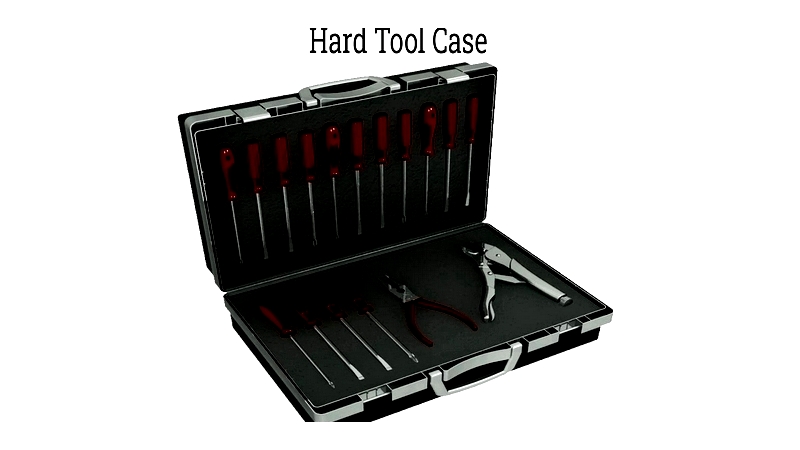
Tool Cases
Tool cases organize and protect hand and power tools with impact-resistant materials. Modular compartments and weatherproof seals cater to technicians across industries, from compact electrician cases to large rolling models.
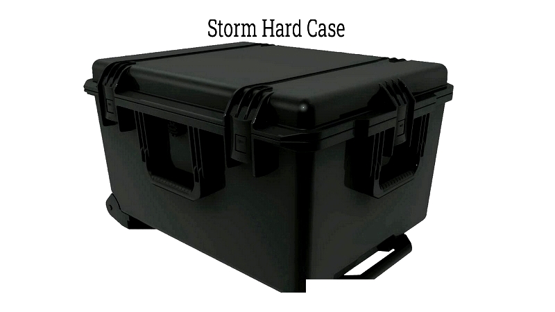
Storm Case
Storm cases withstand extreme weather with watertight seals and reinforced construction. Used by emergency responders and researchers, they feature crush resistance and customizable foam interiors for equipment protection.
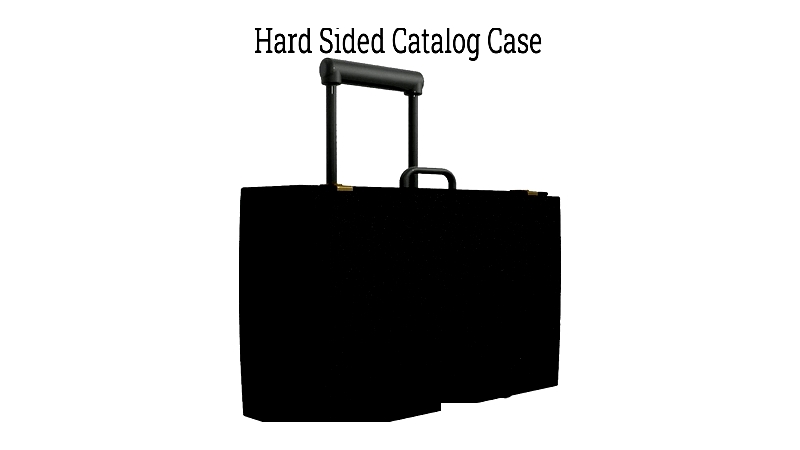
Catalog Cases
Catalog cases transport sales materials and documents with reinforced corners and extendable handles. Compartmentalized interiors maintain organization for professionals attending trade shows.
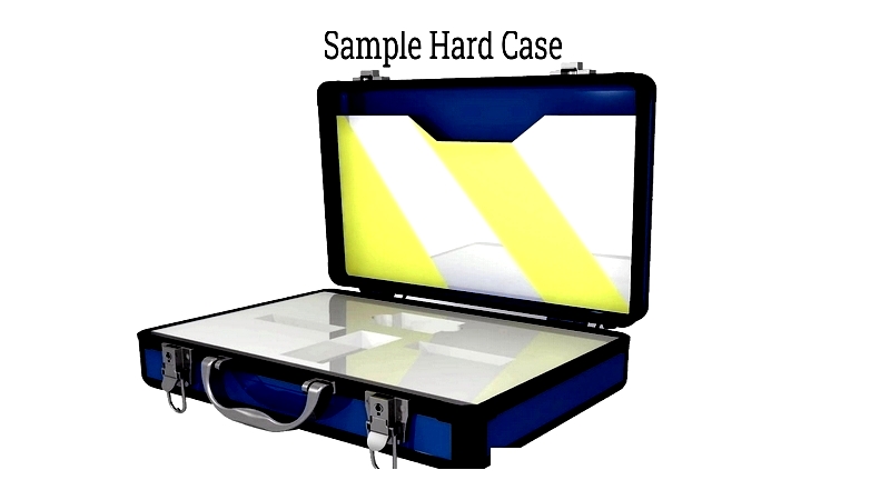
Sample Case
Sample cases showcase products during demonstrations with lockable closures and branding options. Their durable design enhances corporate image while protecting valuable samples.
Case Applications Summary
The twelve hard case types demonstrate the industry's diverse capabilities. Beyond these categories, manufacturers offer custom