Introduction
This article provides comprehensive information about water tube boilers and their applications.
You will learn about:
- What a Water Tube Boiler is
- How Water Tube Boilers Work
- Different Types of Water Tube Boilers
- Applications of Water Tube Boilers
- The Structure of Water Tube Boilers
- And much more...
Chapter 1: What is a Water Tube Boiler?
A water tube boiler features a series of tubes that carry water, heated by hot gases from a furnace or combustion chamber beneath. When fuel burns in the furnace, the resulting gases transfer heat to the metal tubes, warming the water inside. This heated water rises to a steam drum where saturated steam is produced.
Water tube boilers can use various fuels including natural gas, propane, coal, diesel, or heating oil. Traditional boilers operated differently, heating tubes immersed in water through a coal or wood furnace. This method was time-consuming and inefficient, leading to the development of the more effective water tube boiler design where water flows through the tubes.
Chapter 2: How a Water Tube Boiler Works
Traditional water boilers, which heated both water and pipes, were bulky and required significant space. Staff had to start them early each morning before workers arrived, resulting in inefficiencies and higher energy consumption in commercial and industrial settings.
The limitations of traditional boilers—large size, slow startup, and risk of failure—led engineers to develop the water tube boiler. This advanced technology offers better thermal efficiency, higher steam output, improved heat transfer, and reduced fuel consumption compared to fire tube boilers. Modern water tube boilers are also safer, easier to operate, and more compact, making them suitable for various applications from power plants to petrochemical industries.
Early boiler technology faced frequent failures due to inadequate materials that couldn't withstand steam pressure, often causing explosions. Initially, multiple small boilers were needed for community heating. To improve efficiency, larger industrial boilers with higher steam pressure and thermal output were developed for factories, refineries, and power plants. Advances in metallurgy and design later improved their reliability.
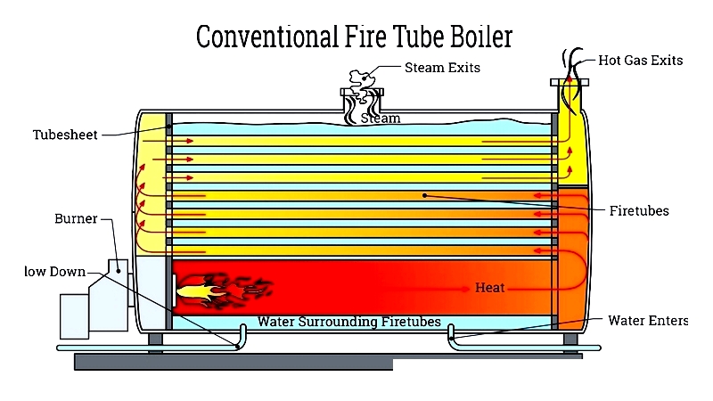
Conventional Boiler
Boilers produce steam by heating water with a burner, utilizing water's excellent heat transfer properties for applications like space heating and electricity generation. In traditional fire tube boilers, tubes are submerged in water, and a furnace heats the tube walls to produce steam. Despite water's efficient heat transfer, conventional boilers consume significant energy due to the lengthy heating process.
Conventional boilers require substantial space, often needing dedicated boiler rooms. This limits their use to large industrial and institutional facilities, making them less suitable for modern manufacturing that demands compact, energy-efficient solutions.
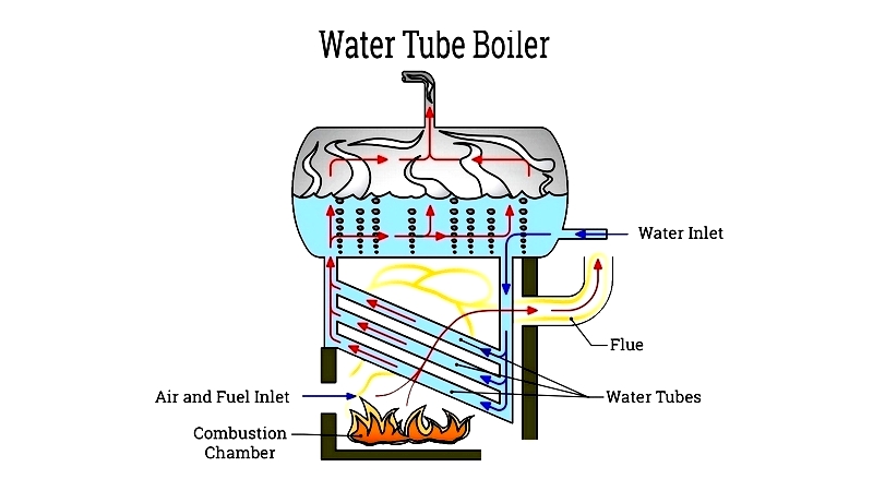
Water Tube Boiler
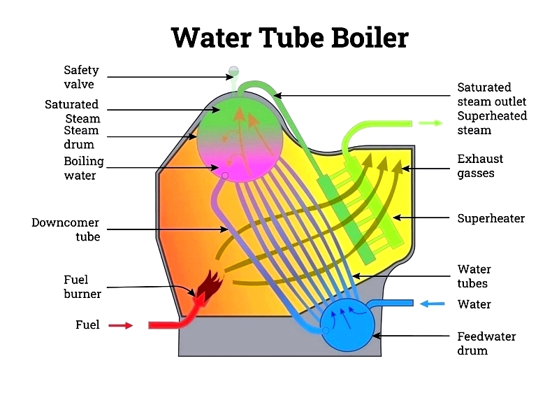
Water tube boilers are popular for their efficiency, quick startup, compact size, and low energy consumption. In this design, water is surrounded by hot gases from the combustion chamber. As these gases pass through the boiler, they heat the water in the tubes, rapidly generating high-pressure steam for electricity production and other needs. Water tube boilers operate efficiently at high pressures and temperatures, making them ideal for power plants and chemical processing facilities.
A typical water tube boiler includes four main components: the water drum (or mud drum), the steam drum, water tubes, the furnace, and either a superheater or economizer. The tubes connect the drums, allowing water to circulate naturally or through forced convection. Cooler water descends through the downcomer tube while heated water rises, ensuring consistent steam quality for various applications.
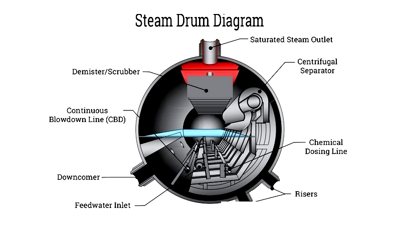
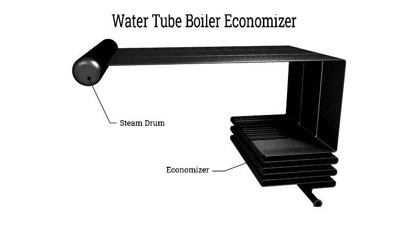
Steam Drum
The steam drum collects and separates steam and water. This large cylinder, made from flat metal plates, is located at the boiler's top. Water from the economizer enters the drum, where a scrubber or demister separates steam from water. Dry steam is distributed for power generation or heating, while water recirculates through downcomers.
Cooler, denser water flows from the steam drum through downcomers to the mud drum at the boiler's base. This movement occurs naturally or is assisted by pumps in high-pressure systems. Steam drums typically have at least six downcomers to ensure proper water flow and prevent overheating.
The mud drum collects sediment and impurities, requiring regular cleaning to maintain efficiency and prevent scaling. Located at the boiler's base, it acts as a reservoir for water treatment.
Water tube boilers feature three main steam drum types: single, bi-drum, and multi-drum. Bi-drum designs are common in industrial boilers for their reliability and ease of maintenance. Single drum boilers, used in large power plants, handle higher pressures and temperatures. Multi-drum boilers offer flexibility and greater steam capacity for heavy industrial use.
Economizer
The economizer, or flue gas heat recovery unit, captures waste heat from exhaust gases to preheat boiler feed water. This improves thermal efficiency and reduces fuel costs, supporting energy management and sustainability goals.
Economizers come in two types: condensing and non-condensing. Condensing economizers are more efficient, recovering latent heat from water vapor condensation, but require corrosion-resistant materials. They cool flue gases below condensation temperature to maximize heat recovery.
Shell-and-tube economizers are widely used, with flue gases passing through the shell and water circulating through tubes. This design suits high-capacity power plants. Plate economizers, with metal plates in parallel or staggered configurations, are ideal for compact systems and retrofits.
Regular economizer maintenance prevents fouling and ensures long-term efficiency, minimizing downtime and maintaining reliable performance.
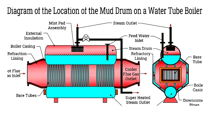
Mud Drum
The mud drum, located at the boiler's base, collects solids and impurities removed through blowdown. Effective blowdown is essential for water treatment, preventing scaling and corrosion.
Water treatment chemicals are added to feed water to protect the steam and mud drums. Treated water enters the boiler from the economizer, absorbing heat before reaching the mud drum. Riser tubes then transport water or steam to maintain circulation, crucial for steam purity and stability.
Proper mud drum design and maintenance are vital for boiler reliability, as buildup can cause inefficiency or tube failure.
Water Tube Burner
Water tube boiler burners feature short flames and wide diameters for efficient combustion. Types include single and multiple flame burners for various fuels. Single flame burners can use two liquid gas fuels, while multiple flame burners are designed for one. These burners include ventilation systems and wind boxes for consistent performance.
Burner performance and emissions depend on oxygen and nitrogen levels, combustion temperature, and NOx residence time. NOx forms at high temperatures, so burner designs focus on reducing emissions through advanced combustion control.
Optimal burner efficiency requires complete combustion, precise fuel-to-air ratio control, and proper mixing