Introduction
This article provides an in-depth examination of power cords.
It covers everything you need to know about power cords and their applications.
You will learn about:
- What is a Power Cord?
- Types of Power Cords
- Classification of Power Cords
- NEMA Standards
- And much more...
Chapter 1: What is a Power Cord?
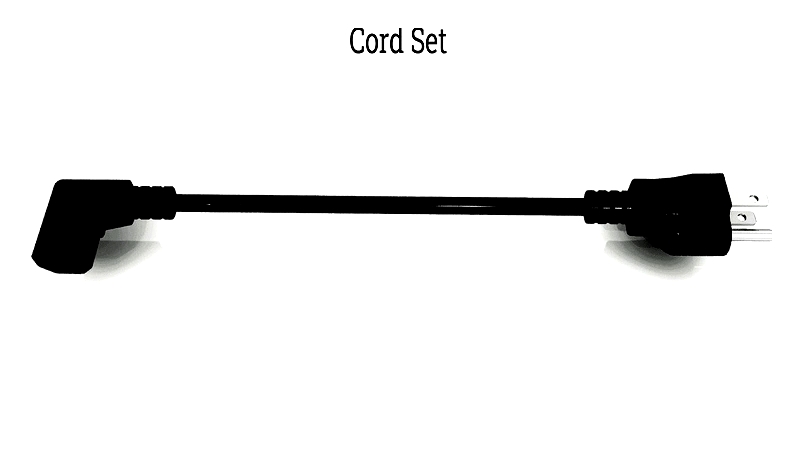
A power cord, also known as a line cord or power cable, serves as a connection between electronic devices and power sources to transmit electricity. These cords typically contain copper wires encased in insulating material and covered with a non-conductive protective layer. They come with standardized plugs that ensure compatibility across different regions. Power cords are generally divided into two types: basic power cords with a plug on one end and bare wires on the other, and connector power cords with a connector on one end and wires on the opposite end.
The National Electrical Manufacturers Association (NEMA) sets design and production standards for electrical plugs, including voltage ratings and socket designs. There are 15 global plug types, labeled Type A to Type O. Electrical suppliers offer various adapters to accommodate these plug variations. In the United States, Type A and Type B plugs are most commonly used.
Power cords typically consist of three main components: a plug, a socket, and the cord itself. Some high-priority cords include locking mechanisms to prevent accidental disconnections, which is particularly important for medical equipment and heavy-duty applications.
Power cords are classified by their voltage or kilovolt capacity, indicating their power transmission capability. The cord's rating depends on its wires, plugs, and connectors, with the lowest-rated component determining the overall rating. The plug also specifies the cord's intended use and manufacturing origin.
A power cord's ability to carry an electrical load depends on its wire gauge and length. The wire's thickness affects its current-carrying capacity and heat generation. Additionally, longer cords experience greater voltage drop—a reduction in voltage from the connector to the cord's end.
The American Wire Gauge (AWG) system assigns a numerical rating to wire thickness. For example, a 12 AWG cord is a 120-volt cord with a 12-gauge wire suitable for 120-volt outlets. In the AWG system, lower numbers indicate thicker wires.
As power cord length increases, so does voltage drop due to power loss from the connector to the far end. Shorter cords maintain stable power levels, while cords longer than 50 feet require higher-rated AWG wires to compensate for increased resistance and minimize significant voltage drop.
The History of the Power Cord
In 1882, Thomas Edison developed a power distribution system by insulating a copper rod with jute, a soft plant fiber. This jute-wrapped rod was placed in a bitumen-lined pipe as part of his project to electrify New York City.
Although vulcanized rubber was invented in 1844, its use in electrical wiring didn't begin until 1880. Rubber-coated cords were standard until the 1930s when armored cable became popular due to its durability, though it remained expensive until the 1950s. It was eventually replaced by two-wire PVC insulated cables.
Today, PVC-coated cords dominate the market due to their high-temperature resistance and durability. PVC has proven to be an effective and robust material for power cord manufacturing.
Chapter 2: What are the different types of power cords?
Understanding power cord types is essential for anyone working with electrical systems or devices requiring safe, reliable power connections. Unlike other equipment categories, power cords aren't universally standardized but vary by regional electrical codes and infrastructure. Global differences in outlets, voltages, frequencies, and plug shapes make cord compatibility crucial for industrial and residential use. Proper knowledge helps businesses, travelers, and manufacturers select cords that meet international safety and compliance standards.
International travelers with devices like laptops or smartphones quickly notice plug and power supply differences, as each country has its own standards. There are 14 global plug types, labeled Type A through Type N. Organizations like IEC, NEMA, and CEE set standards for these plugs, defining specifications for connectors, voltage ratings, safety features, and designs to ensure safety and compatibility across different power environments.
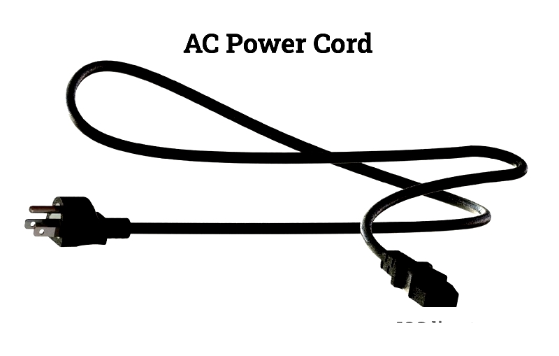
AC Power Cords
AC power cords are the most common cables for supplying alternating current from power sources to electrical equipment. Designed for standard voltages, they're used in power tools, lighting, HVAC systems, computers, electronics, kitchen appliances, musical instruments, and shop equipment.
AC power cords contain copper or aluminum wires, polymer or rubber insulation, and molded plugs with prongs, casings, and sometimes fuses. Their voltage ratings, wire gauge, shape (flat or round), length, sheathing material, and plug type are standardized for specific uses. The connector interfaces with the device while the plug connects to wall outlets or power distribution units in industrial settings.
Since electrical systems operate at different voltages (100V-240V) and frequencies (50Hz-60Hz), power cords must match local standards. AC plugs are categorized internationally as Type A through Type O, with country-specific variations. For global operations, understanding these distinctions is critical to avoid equipment failure or safety hazards.
Modern AC cords include grounding and polarization for enhanced safety. Grounded cords reduce shock risks and are essential for high-wattage devices. Polarization ensures proper connection to the circuit's neutral side. Safety certifications like UL, CSA, VDE, or CE should be verified when purchasing cords for sensitive equipment in labs or healthcare settings.
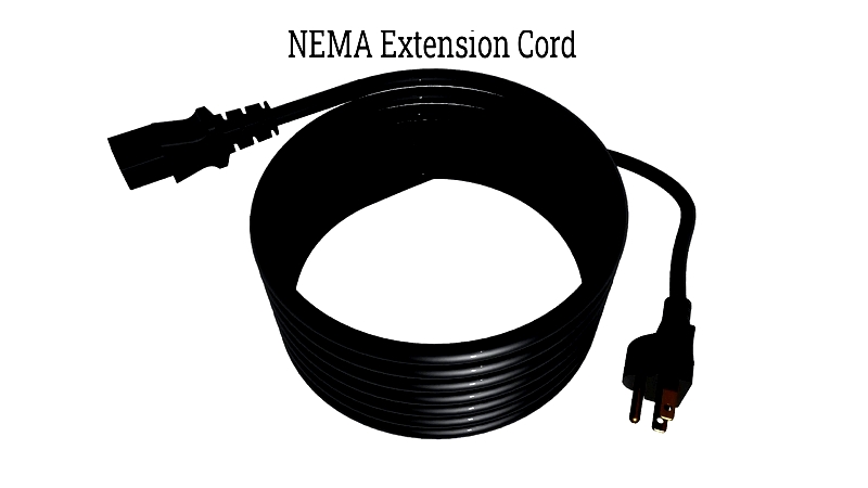
NEMA Power Cords
NEMA power cords follow North American standards for plugs, voltage capacities, and receptacle configurations. Common NEMA plugs include Type A (2-prong) and Type B (3-prong with ground), widely used in U.S., Canadian, and Mexican homes and businesses. While Type A plugs are being replaced by grounded Type B, some devices still support both for backward compatibility. International standards like IEC C13 and C19 connectors are common in IT and data centers.
NEMA-compliant devices use one-wire or two-wire systems, with grounding for safety and surge protection. When selecting components, consider the application (industrial, household), plug configuration, energy load (amps/watts), and power delivery requirements. Note that NEMA standards only apply in North America; international travelers may need adapters and voltage converters.
NEMA connectors come in straight blade and locking types. Straight blade connectors, common in electronics and appliances, have flat or folded metal prongs with a rounded ground pin. Locking connectors, used commercially and industrially, feature curved blades and twist-lock mechanisms to prevent accidental disconnections, crucial for industrial environments and heavy-duty extension cords.
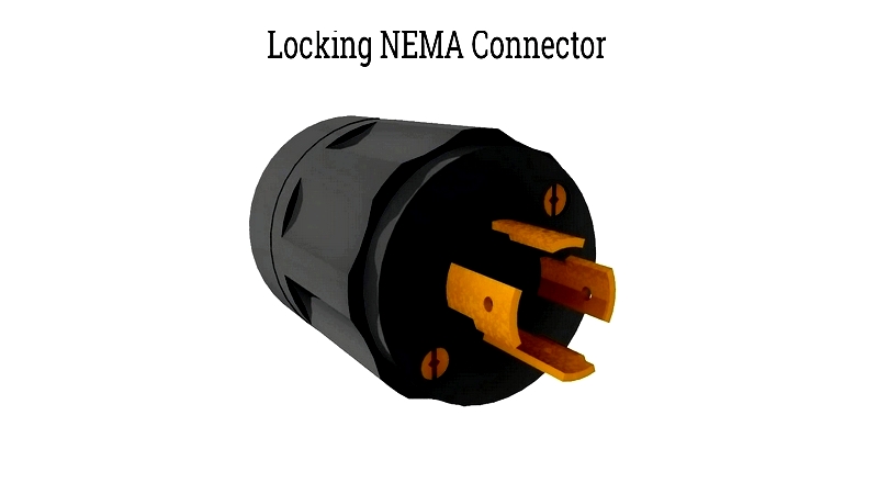
NEMA non-locking straight connectors have 25 subtypes, while locking connectors have 24. Each subtype has a unique code (e.g., NEMA 5-15P, NEMA L14-30P) indicating power capacity, grounding, and intended use, helping professionals source the right replacement cords.
NEMA 5-15P Power Cords
NEMA power cords range from 15 to 60 amps and 125 to 600 volts, each with specific classifications. NEMA 1 cords have two-prong, non-grounded designs, while NEMA 5 cords feature three-prong grounded configurations. NEMA 5 cords, common in homes and offices, support up to 125 volts. The NEMA 5-15 is a grounded version of NEMA 1-15, widely used for computers and small appliances. Higher classifications like NEMA 6 are for industrial machinery or large appliances requiring greater current and voltage.
While all NEMA 5-15P cords have three prongs, some have